
A place and route tool reads a handful of standard files and writes another handful. Knowing what each file holds makes the rest of physical design much easier to follow: the netlist says what to build, Liberty says how fast and power-hungry each cell is, LEF says how big each cell is and what the metal layers look like, SDC says how fast the design must run, and DEF and GDSII describe the result. This article goes through each file with a real excerpt from the sky130 library and the 8-bit counter.
8 min read | Beginner
What You'll Learn
- Name the input files of place and route and what each one provides
- Read short excerpts of a netlist, a Liberty file and a LEF file
- Name the output files and who uses them
- Explain why the same cell appears in three different files
The Big Picture
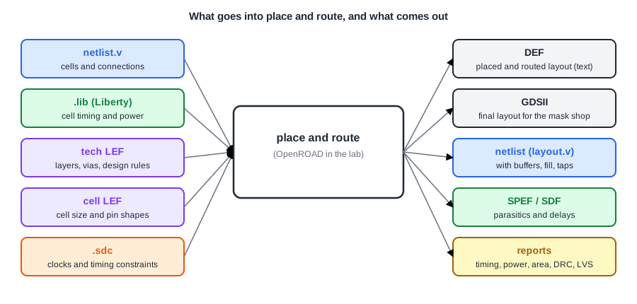
The same standard cell, say sky130_fd_sc_hd__and3_1, appears in three input files, each with a different view of it: the netlist uses it, the Liberty file describes its timing and power, and the cell LEF describes its outline and pin shapes. The tool links them by the cell name.
The Netlist
The gate-level Verilog netlist from synthesis lists the instances and the nets between their pins:
sky130_fd_sc_hd__and3_1 _22_ (
  .A(\q[3] ),
  .B(\q[4] ),
  .C(_09_),
  .X(_10_)
);
Instance _22_ is a three-input AND gate whose output drives net _10_. Place and route keeps this connectivity but may add instances (clock buffers, tap cells, fillers) and change cells to stronger ones to fix timing.
Liberty: Timing and Power
The Liberty file (.lib) describes each cell electrically, for one process corner: here typical silicon, 25 C and 1.80 V (sky130_fd_sc_hd__tt_025C_1v80.lib). An excerpt for the same AND gate:
cell ("sky130_fd_sc_hd__and3_1") {
    area : 6.2560000000;
    cell_footprint : "sky130_fd_sc_hd__and3";
    pin ("A") {
        capacitance : 0.0014760000;
        direction : "input";
    }
    ...
}
The area is in um2 and the pin capacitance in pF. Further down are tables of delay and output slew against input slew and output load, plus leakage and internal power. Place and route uses Liberty for every timing-driven decision: buffering, sizing, CTS and the final timing report. The Standard Cell Libraries and Liberty article of the STA tutorial explains the tables in detail.
LEF: Geometry
LEF (Library Exchange Format) comes in two parts. The technology LEF describes the process: the routing layers, their direction, pitch and width, the vias, and the placement site. The cell LEF describes each cell as an abstract: its size, its pins and the metal it uses inside (obstructions). The same AND gate:
MACRO sky130_fd_sc_hd__and3_1
  CLASS CORE ;
  SIZE  2.300000 BY  2.720000 ;
  SITE unithd ;
  PIN A
    DIRECTION INPUT ;
    USE SIGNAL ;
    PORT
      LAYER li1 ;
        RECT 0.085000 0.635000 0.635000 1.020000 ;
    END
  END A
  ...
The cell is 2.30 um wide and 2.72 um tall, and 2.30 x 2.72 is exactly the 6.256 um2 of the Liberty file. Pin A is a rectangle on the li1 layer, where the router must connect to it. The LEF has no transistors; the full layout of each cell is only merged in when the GDSII is written. The Technology LEF and Cell LEF articles go deeper.
Quick Check
Q: Which file tells the tool how wide dfxtp_1 is, and which tells it how long its clock-to-Q delay is?
Show Answer
The width (7.36 um) comes from the cell LEF. The clock-to-Q delay comes from the Liberty file, as a table that depends on the clock slew and the load on Q.
SDC: Constraints
SDC (Synopsys Design Constraints) defines the clocks, the input and output delays and any timing exceptions. A minimal constraint for the counter:
create_clock -name clk -period 5.0 [get_ports clk]
set_input_delay  1.0 -clock clk [get_ports {rst en}]
set_output_delay 1.0 -clock clk [get_ports q*]
Every timing-driven step reads these constraints. In the lab's PnR panel the clock period is a field of the panel, and the flow creates the clock from it with the same create_clock command.
The Outputs
- DEF (Design Exchange Format): the placed and routed design as text, with the die area, rows, every component with its position, the pins, the power network and every routed wire. A placed cell looks like
- _22_ sky130_fd_sc_hd__and3_1 + PLACED ( 21160 27200 ) N ;, with coordinates in nanometres (1000 database units per micron). See DEF: The Layout Database in Text Form. - GDSII: the final layout as polygons on numbered layers, with the cell layouts merged in. This is what the foundry receives.
- Netlist after layout (
layout.v): the netlist with every cell the flow added, used for LVS and gate-level simulation. - SPEF and SDF: wire parasitics, and back-annotated delays for gate-level simulation.
- Reports: timing, power, area, CTS, IR drop, antenna, DRC and LVS.
OpenROAD also writes its own database file (.odb), which holds everything in one binary file and is what later steps reload.
Quick Check
Q: A DEF file shows PLACED ( 21160 27200 ) with UNITS DISTANCE MICRONS 1000. Where is the cell?
Show Answer
At x = 21.16 um, y = 27.20 um: the coordinates are in database units, 1000 per micron. That is the lower-left corner of the cell (for orientation N).
Running It in ChipVerify Lab
Run synthesis and Place and Route on the counter, then look at the outputs: the synthesized netlist in the synthesis panel, and the final netlist, the timing report and the layout in the PnR report. The GDSII can be downloaded from the report.
Common Mistakes
Mistake #1: Mixing libraries or corners
The Liberty, the LEF and the netlist must come from the same library. A netlist synthesized for one library and placed with the LEF of another fails to link, or worse, links cells with the wrong sizes.
Mistake #2: Forgetting the constraints
Without a clock definition, place and route has no timing goals: it does not repair timing or build a timed clock tree, and every timing report is empty. Always check that the clocks were created.
Practice Exercise
Challenge: Find the Added Cells in the Netlist
Run Place and Route on the counter and look at the final netlist. Find the instances that were not in the synthesized netlist. How can you tell them apart by name?
Hint
Look at the instance names: synthesis names cells _NN_; the physical design steps use their own prefixes.
Solution
CTS names its buffers after the clock net: clkbuf_0_clk, clkbuf_1_0__f_clk and clkbuf_1_1__f_clk. The tap cells are named TAP_TAPCELL_ROW_... and the fillers FILLER_.... In the counter there are 3 clock buffers, 5 tap cells and 73 fillers next to the 28 synthesized cells.
Open the ready-made example in the lab, synthesize it and run Place and Route.
Summary
- Inputs: the netlist (what to build), Liberty (timing and power), technology and cell LEF (geometry) and SDC (constraints).
- The tool links the three views of each cell by name; LEF and Liberty must come from the same library.
- Outputs: DEF (layout as text), GDSII (for the foundry), the final netlist, SPEF and SDF, and reports.
- DEF coordinates are in database units, 1000 per micron for sky130.
