
Electromigration (EM) is the slow movement of metal atoms in a wire that carries a high current density. Over months and years it thins a wire until it breaks, or piles up metal until it shorts to a neighbour. A chip that works on the first day can fail in the field because of it. This article explains what electromigration is, how a process sets its limits, and checks the power grid of the 16x16 multiplier against the sky130 limits, wire by wire and via by via.
8 min read | Intermediate
What You'll Learn
- Explain what electromigration does to a wire and why it depends on current density
- Read the EM limits of a technology LEF
- Compare the currents in a power grid with those limits
- Find the weakest point of a grid: wires or vias
Current Moves Metal
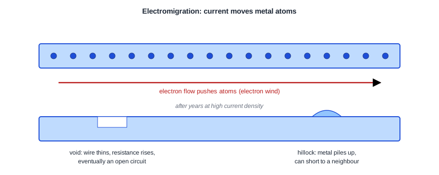
Electrons flowing through a metal wire collide with the metal atoms and push them along, a little at a time: the "electron wind". Where more atoms leave a spot than arrive, a void forms; the wire gets thinner, its resistance rises and it can finally open. Where atoms pile up, a hillock grows that can touch the next wire.
The rate depends on the current density, the current per cross-section of the wire, and strongly on temperature. A wire that carries a modest current for 10 years at 90 °C may be fine; twice the current density can shorten its life many times over. That is why EM is a reliability check, not a functional one: the chip works in the lab and fails later.
Power wires are the most exposed. They carry current in one direction all the time, which is the worst case for EM. Signal wires carry current back and forth, which partly heals the damage, so their limits are higher and given as RMS values.
The Limits in sky130
The foundry measures how much current each layer and via can carry for the target lifetime, and the tech LEF records it. For sky130, at a junction temperature of 90 °C:
| Layer | Average current limit |
|---|---|
| met1, met2 | 2.8 mA per um of width |
| met3, met4 | 6.8 mA per um |
| met5 | 10.17 mA per um |
| mcon (li1 to met1) | 0.36 mA per via |
| via (met1 to met2) | 0.29 mA per via |
| via2, via3 | 0.48 mA per via |
| via4 (met4 to met5) | 2.49 mA per via |
In the LEF they appear as, for example, DCCURRENTDENSITY AVERAGE 2.8 ; under LAYER met1. Wire limits scale with the width: a 0.48 um met1 rail may carry 0.48 x 2.8 = 1.34 mA, a 1.6 um met4 strap 10.9 mA, a 1.6 um met5 strap 16.3 mA. Via limits are per cut, so an array of five vias carries five times the limit of one.
Quick Check
Q: A met1 rail must carry 2 mA. How wide must it be?
Show Answer
2 / 2.8 = 0.71 um at least. A rail of the standard 0.48 um width cannot carry it: either the current must be split, by feeding the rail from straps more often, or the rail made wider.
The Multiplier's Grid
With the -enable_em option, OpenROAD's power analysis writes the current in every segment of the grid to a file:
analyze_power_grid -net VDD -enable_em -em_outfile em_vdd.rpt
Each line is one resistor of the grid: two nodes with their layer and position, and the current between them. The highest currents per layer on VDD, for the multiplier at 16 mW with straps every 27 um:
| Element | Highest current | Limit | Use of limit |
|---|---|---|---|
| met1 rail, 0.48 um | 0.241 mA | 1.34 mA | 18 % |
| met4 strap, 1.6 um | 0.687 mA | 10.9 mA | 6 % |
| met5 strap, 1.6 um | 1.835 mA | 16.3 mA | 11 % |
| met1 to met2 via array, 5 cuts | 0.361 mA | 5 x 0.29 = 1.45 mA | 25 % |
| met2 to met3 via array, 4 cuts | 0.361 mA | 4 x 0.48 = 1.92 mA | 19 % |
| met4 to met5 via, 1 cut | 1.442 mA | 2.49 mA | 58 % |
The via array sizes come from the DEF, where pdngen records the via it generated for each crossing, for example ROWCOL 1 5 for the met1-met2 array and a single 0.8 um cut for via4.
Reading the Results
Every element is within its limit, but not by the same margin. The wide straps are barely used: 6 and 11 %. The weakest point is the single via4 cut between a met4 and a met5 strap, at 58 %. The current from a bump enters the met5 straps and must pass down to met4 through these few crossings, so each one carries a lot.
That is a common result: in a power grid, the vias between the top layers are often closer to their EM limit than the wires. If the multiplier ran at twice the current, the via4 cuts would exceed their limit while every wire still had plenty of margin. The fix would be a larger via4 array, which needs wider straps at the crossing, or more crossings.
The rails are fine at 18 %, because a strap of their own net feeds them every 27 um, so no rail carries current further than about 13.6 um. With straps every 54 um each rail would carry current over a longer distance, and its highest current would rise.
Quick Check
Q: The met1-met2 and met3-met4 via arrays in the same stack carry the same current, 0.361 mA. Why is the met1-met2 array closer to its limit?
Show Answer
Its via type has a lower limit per cut: 0.29 mA for via against 0.48 mA for via3. Even with five cuts against four, the met1-met2 array is at 25 % and the met3-met4 array at 19 %.
Signal EM
EM also applies to signal wires, especially clock nets and the outputs of strong drivers, which switch every cycle into a large load. Their limits are RMS currents (ACCURRENTDENSITY RMS in the LEF, 6.1 mA per um on met1). Commercial flows check them after routing and widen or double the affected wires. The lab's flow checks only the power grid.
Running It in ChipVerify Lab
EM results need a connected power grid with straps; with the rails-only grid of the lab's default flow the power analysis stops before any current is computed. With PRO, add -enable_em -em_outfile to the VDD analysis in a custom script with a full grid, as in Building a PDN in OpenROAD, and sort the output file by its last column to find the highest currents.
Common Mistakes
Mistake #1: Checking only the wires
In the multiplier the wires used at most 18 % of their limits while a via4 cut used 58 %. Always check the vias too.
Mistake #2: Using a typical-temperature limit
EM limits fall steeply with temperature. Use the limits at the junction temperature the chip will actually reach; the sky130 LEF values are for 90 °C.
Mistake #3: Checking EM at average activity
Like IR drop, EM scales with current. Check at the worst realistic activity, not at the default toggle rate.
Practice Exercise
Challenge: How Much Margin?
By what factor could the multiplier's power rise before the first element of its grid exceeds its EM limit? Which element would fail first, and how would you fix it?
Hint
All currents scale with the power. Find the element with the highest use of its limit.
Solution
The via4 cut is at 58 %, so the power could rise by about 1 / 0.58 = 1.7 times, to roughly 27 mW. The via4 cuts fail first. A larger via4 array at each crossing (wider straps, so more cuts fit) or more met4/met5 crossings (a smaller strap pitch) would spread the current.
Open the ready-made example in the lab, synthesize it and run Place and Route.
Summary
- Electromigration moves metal atoms under high current density and makes wires fail over years.
- The tech LEF gives average limits per um of width for wires and per cut for vias, at a stated temperature.
analyze_power_grid -enable_emwrites the current of every grid segment.- In the multiplier the wires used at most 18 % of their limits, but a single via4 cut used 58 %.
- Vias between the top layers are often the weakest point of a power grid.
