
After routing, a layout still has empty space: gaps between cells in the rows, and large areas of the upper metal layers with no wires at all. Manufacturing needs both filled. Filler cells close the gaps in the rows so that the wells and power rails run continuously, and metal fill adds dummy shapes so that every layer has an even density of metal for polishing. This article shows both on the routed 16x16 multiplier and explains the density rules behind metal fill.
6 min read | Intermediate
What You'll Learn
- Explain why every gap in the rows is filled with filler cells
- Describe why metal density must be even and what metal fill adds
- Run density fill in OpenROAD and read its result
- Explain how fill interacts with timing and with the rest of the flow
Filler Cells
A standard cell row is more than a line of cells. Every cell contains a piece of the n-well, the p-type region, and the met1 power rails at its top and bottom edges. A gap between two cells would break all of them. Filler cells are cells with no transistors that contain just those layers, so placing them in every gap makes the wells, implants and rails continuous along the row.
The lab's flow runs filler_placement at the end, with the four sky130 filler cells of 1, 2, 4 and 8 sites:
[INFO DPL-0001] Placed 2435 filler instances.
| Filler cell | Width | Count in the multiplier |
|---|---|---|
| sky130_fd_sc_hd__fill_8 | 8 sites | 879 |
| sky130_fd_sc_hd__fill_4 | 4 sites | 473 |
| sky130_fd_sc_hd__fill_2 | 2 sites | 549 |
| sky130_fd_sc_hd__fill_1 | 1 site | 534 |
Together they cover 10,556 of the core's 18,872 sites (56 rows of 337 sites), so the logic, the antenna diodes and 319 tap cells take the other 44 %, the same 44 % utilization the run reports. The placer uses the widest fillers first and closes the rest with narrow ones, which keeps the instance count low.
Some flows use decap cells for part of the empty space instead: filler cells that also contain a capacitor between VDD and VSS, which smooths the supply locally, as described in Tap Cells, Endcaps and Decaps. The lab's flow uses plain fillers unless the PRO Decap option is set.
Quick Check
Q: Filler cells are placed after routing. Why does that not disturb the routes?
Show Answer
Filler cells contain only wells, implants and the power rails, which are already drawn by the power grid's followpin rails. They have no pins and no internal met1 shapes that a signal route could touch, so they fit into the gaps without creating shorts or spacing violations with the routed wires.
Why Metal Density Matters
Each metal layer is made by depositing metal over the whole wafer and polishing it flat with chemical-mechanical polishing (CMP). Polishing removes material at a rate that depends on how much metal is in the area around it. Areas with very little metal are polished deeper (dishing), areas with a lot of metal stay higher, and the surface for the next layer is no longer flat. Thickness changes alter wire resistance, and an uneven surface makes the next layer harder to print.
Foundries therefore specify density rules for each metal layer: the share of the area covered by metal must stay between a minimum and a maximum inside every checking window, typically windows tens to hundreds of micrometres wide moved across the die. The sky130 rule documentation lists such rules for the metal layers.
The routed multiplier is far from even. Over the whole 175 um die, with the met1 rails and the met4 and met5 straps of the power grid from Building a PDN in OpenROAD:
| Layer | Signal wires | Power grid | Fill added | Total after fill |
|---|---|---|---|---|
| met1 | 6.0 % | 13.8 % | 0 % | 19.8 % |
| met2 | 6.5 % | 0.6 % | 2.4 % | 9.5 % |
| met3 | 0.6 % | 0.5 % | 19.8 % | 21.0 % |
| met4 | 0.1 % | 8.6 % | 23.8 % | 32.5 % |
| met5 | 0 % | 7.1 % | 8.9 % | 16.0 % |
Without fill, met3 is 1 % metal. Almost all of it is in a few wires, and most windows on met3 are completely empty.
Density Fill in OpenROAD
OpenROAD adds metal fill with density_fill, driven by a JSON file of fill rules per layer: the allowed fill square sizes, the spacing between fill shapes, and the spacing to real shapes. OpenROAD-flow-scripts ships one for sky130 (platforms/sky130hd/fill.json). For met3 it allows squares of 2.0, 1.0, 0.58 and 0.4 um, 0.3 um apart, and at least 3 um from any non-fill shape. It also keeps fill 70 um away from the die edge, which suits a full chip; for this 175 um block that would leave only a small square in the middle, so the run below reduced that keep-out to 5 um:
density_fill -rules fill5.json
[INFO FIN-0003] Filling layer met3.
[INFO FIN-0009] Filling 45 areas with non-OPC fill.
[INFO FIN-0004] Total fills: 4077.
The "Total fills" count is cumulative over the layers. In all, 7,790 fill shapes were added: 633 on met2, 3,444 on met3, 3,409 on met4 and 304 on met5. In the DEF they appear in a separate FILLS section, not as nets.
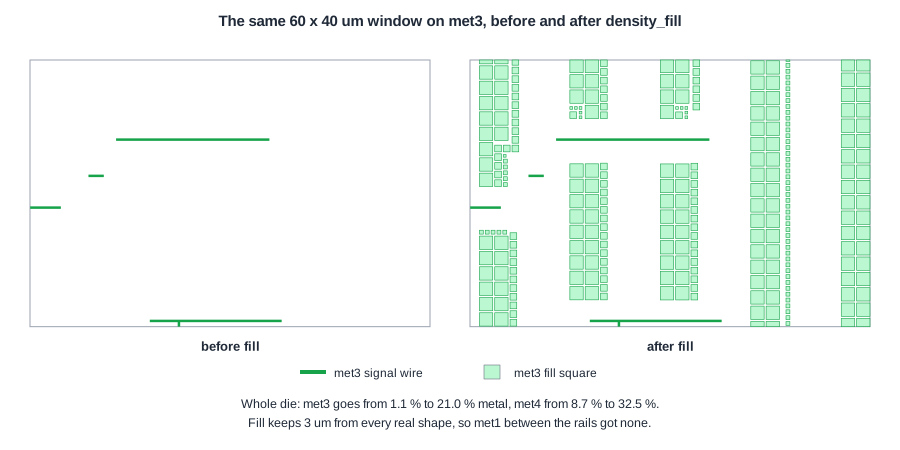
The fill squares surround the met3 wires with the 3 um gap, and the larger squares fill open areas while the small ones fill the leftovers. The empty vertical bands are where the power grid's via stacks pass through met3. met1 got no fill at all: the met1 rails are 2.72 um apart, so no point between them is 3 um from a real shape.
Fill and Timing
Fill shapes are metal next to signal wires, so they add capacitance. Two choices keep that under control:
- Spacing to real shapes. The 3 um keep-out in the sky130 rules is large compared with the wire spacing, so fill adds little capacitance to the wires next to it.
- Floating fill. The fill squares are not connected to any net. Floating metal adds less capacitance than grounded metal, but extraction has to model it to be exact.
Because of this, fill is added after timing closure, and the final extraction and timing check run on the filled layout. Any later change to the routing means removing and reinserting the fill near the change.
Quick Check
Q: met4 was already 8.6 % metal from the power straps, yet fill added another 23.8 % there, more than on any other layer. Why so much?
Show Answer
The power straps cover narrow vertical bands; between them met4 was almost empty, since signals used only 0.1 % of it. Fill works on the free area, and met4 had large free regions between the straps where the biggest 2 um squares fit, so it received the most fill.
Running It in ChipVerify Lab
Run Place and Route on the multiplier, find the filler placement line in the log and open the layout with the filler cells shown. The report has a metal density section for every run; for the multiplier it shows 21 % on met1, 7 % on met2, 2.5 % on met3, 10 % on met4 and 7 % on met5. The KLayout DRC deck of the flow does not check density rules.
With PRO, the Metal Fill option runs density_fill with the sky130 rules after the filler cells. On the multiplier it added 6,608 fill shapes, 758 on met2, 2,936 on met3, 2,610 on met4 and 304 on met5, which appear in the FILLS section of the DEF. They are streamed into the GDSII with the rest of the layout, and the density section of the report shows the difference: met2 rises from 7 % to 10 %, met3 from 2.5 % to 16 %, met4 from 10 % to 24 % and met5 from 7 % to 16 %.
Common Mistakes
Mistake #1: Leaving gaps in the rows
A missing filler breaks the n-well, the implants and the power rails along the row, and DRC flags the gap.
Mistake #2: Adding metal fill before timing is final
Fill blocks routing tracks and adds capacitance. Insert it after the last routing change, then extract and check timing again.
Mistake #3: Using a full-chip fill setup on a block
Settings such as a 70 um keep-out from the edge are meant for a chip with a pad ring, like the one in Building the Pad Ring. On a small block they leave most of it unfilled.
Practice Exercise
Challenge: Filler Area
A sky130 hd site is 0.46 x 2.72 um. The multiplier used 879 fill_8, 473 fill_4, 549 fill_2 and 534 fill_1 cells. What area do the filler cells cover, and what share of the 23,613 um2 row area is that?
Hint
Count sites first: each fill_N cell is N sites wide.
Solution
Sites: 879 x 8 + 473 x 4 + 549 x 2 + 534 x 1 = 7,032 + 1,892 + 1,098 + 534 = 10,556. Area: 10,556 x 0.46 x 2.72 = 13,208 um2, which is 56 % of the row area. The other 44 % is the logic and tap cells, matching the reported utilization.
Open the ready-made example in the lab, synthesize it and run Place and Route.
Summary
- Filler cells close every gap in the rows so wells, implants and rails stay continuous; the multiplier needed 2,435 of them.
- Metal density must stay within limits in every window for CMP to give a flat surface.
density_filladded 7,790 floating fill squares, raising met3 from 1 % to 21 % metal.- Fill keeps a margin from real shapes and is inserted after timing closure, followed by final extraction.
