
Digital design is the craft of building electronic circuits that work with just two values, 0 and 1. Everything a computer does - showing a photo, adding numbers, playing a song - is broken down into enormous numbers of these simple values, moved around and combined by tiny switches called transistors. This tutorial explains what "digital" means, how switches can make decisions, and how the pieces stack up into a complete chip.
12 min read | Beginner Level
What You'll Learn
- What "digital" means, and why computers use only 0s and 1s
- How simple switches can make logical decisions such as AND and OR
- What a transistor and a logic gate are, in plain terms
- How a chip is built up in layers, and how this series walks through them
Analog vs. Digital
Think of two ways to control a light. A dimmer knob can set the brightness to any level - a little, a lot, or anything in between. A normal light switch has only two positions: on or off.
Electronics has the same two styles:
| Analog | Digital | |
|---|---|---|
| Everyday example | Dimmer knob, a vinyl record, a mercury thermometer | Light switch, a music file, a digital clock |
| Values allowed | Any value in a smooth range | Only two: 0 and 1 |
| Effect of a little noise | Changes the value slightly, and the error adds up | Usually no effect at all |
| Copying | Every copy is slightly worse | Copies are perfect |
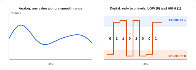
The big advantage of digital is in that third row. A digital circuit only has to tell "clearly high" from "clearly low". A small wobble in the voltage does not change a 1 into a 0, so the information survives being sent, stored, and copied millions of times.
Bits: The 0s and 1s
A single 0-or-1 value is called a bit (short for binary digit). Inside a circuit, a bit is just a voltage on a wire:
- 0 (LOW): a voltage close to zero.
- 1 (HIGH): a voltage close to the supply voltage - around 1 volt inside a modern chip, or 3.3 V or 5 V on many circuit boards.
One bit can only say yes or no. Groups of bits can say much more, because every extra bit doubles the number of possible patterns:
| Number of bits | Possible patterns | Enough for |
|---|---|---|
| 1 | 2 | Yes / no, on / off |
| 2 | 4 | The four seasons |
| 8 (one byte) | 256 | One letter of text, or one shade of one colour |
| 24 | about 16.7 million | The colour of one pixel on your screen (8 bits each for red, green, and blue) |
Counting with 3 bits: every pattern is a different value

  000  001  010  011  100  101  110  111
   0    1    2    3    4    5    6    7

  3 bits -> 2 x 2 x 2 = 8 patterns
Quick Check
Q: How many different patterns can 4 bits make?
Show Answer
16. Each bit doubles the count: 2 x 2 x 2 x 2 = 16 (the patterns 0000 through 1111).
Switches Can Make Decisions
Here is the key idea of the whole subject: switches wired together can make logical decisions. Take a battery, a lamp, and two switches, A and B:
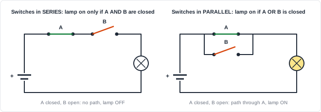
- In series (one after the other), current can only flow if A and B are both closed. The lamp is on only when A AND B are on.
- In parallel (side by side), current flows if either switch is closed. The lamp is on when A OR B is on.
If we write "closed" and "lamp on" as 1, and "open" and "lamp off" as 0, we can list every possibility in a truth table:
| A | B | Series (A AND B) | Parallel (A OR B) |
|---|---|---|---|
| 0 | 0 | 0 | 0 |
| 0 | 1 | 0 | 1 |
| 1 | 0 | 0 | 1 |
| 1 | 1 | 1 | 1 |
Where Do You See This Every Day?
A bank vault that needs two keys turned at once is an AND. A staircase light that can be switched on from the top or the bottom is an OR. A microwave that only runs when the door is closed AND the start button is pressed is logic too. Inside a chip, the same decisions are made by electronic switches instead of hand-operated ones.
Transistors: Switches Controlled by Electricity
A light switch needs a finger to flip it. A transistor is a switch that is flipped by a voltage instead. Put a HIGH voltage on its control input and it connects; put a LOW voltage on it and it disconnects (or the other way round, for the other type of transistor).
That one property changes everything. Because a transistor is controlled by a voltage, and its output is a voltage, one transistor can control another. Chains of transistors can make decisions with no human involved, millions or billions of times per second.
Modern transistors have no moving parts and are astonishingly small. More than a thousand of them could sit side by side across the width of a single human hair, which is how a fingernail-sized chip can hold billions of them.
Logic Gates: Small Circuits With a Job
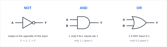
A handful of transistors wired together to perform one basic decision is called a logic gate. Three gates are enough to start with:
| Gate | Rule | Everyday version |
|---|---|---|
| NOT | Output is the opposite of the input | "Turn the warning light on when the door is NOT closed" |
| AND | Output is 1 only if all inputs are 1 | Two-key vault |
| OR | Output is 1 if any input is 1 | Staircase light with two switches |
By connecting gates together, you can build anything: circuits that add numbers, circuits that choose between signals, and circuits that remember a bit. Memory circuits, combined with a steady ticking signal called a clock, let a chip work step by step - which is how a processor follows a list of instructions.
Quick Check
Q: A car's seatbelt warning should sound when someone is in the seat AND the belt is NOT buckled. Which gates do you need?
Show Answer
A NOT gate on the "belt buckled" signal, and an AND gate combining it with "seat taken". The warning is 1 only when the seat is taken (1) and the belt is not buckled (NOT 0 = 1).
Describing Hardware
Nobody draws billions of transistors by hand. Designers describe the behaviour they want in a hardware description language (HDL) such as Verilog, and software tools turn that description into gates and transistors. The description of the seatbelt warning is really just the rule itself:
Seatbelt warning

  ALARM = SEAT_TAKEN AND (NOT BELT_ON)

  SEAT_TAKEN : 1 when someone is sitting in the seat
  BELT_ON    : 1 when the seatbelt is buckled
  ALARM      : 1 when the warning should sound
What comes out of the tools? A program called a synthesis tool reads the description and produces the actual circuit: here, one NOT gate and one AND gate (often combined into a single small ready-made gate). The same idea scales up to descriptions of entire processors. This series stays at the level of gates, timing and circuits; the Verilog language itself is taught in its own tutorials.
The Big Picture: A Chip Is Built in Layers
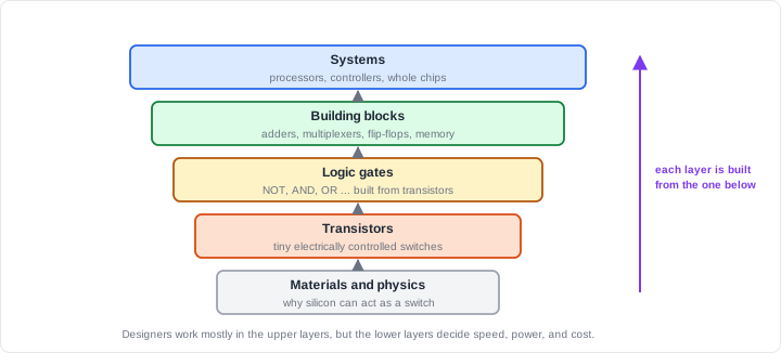
A chip is easier to understand as a stack of layers. Each layer is built from the one below it, and each one hides the details underneath, so designers can think about gates or whole blocks instead of individual electrons:
| Layer | The question it answers |
|---|---|
| Materials and physics | Why can a piece of silicon act as a switch at all? |
| Transistors | How does a voltage turn a switch on and off, and how fast? |
| Logic gates | How are transistors arranged to make NOT, AND, OR, and more? |
| Building blocks | How do gates combine into adders, selectors, memory, and counters? |
| Systems and chips | How do blocks, timing, wires, and power come together into a real, manufacturable chip? |
This series climbs that ladder from the bottom. It starts with why silicon can conduct electricity in a controllable way, moves through transistors and gates, and ends with the steps that turn a Verilog description into a finished chip. Along the way, the focus is always on intuition: what goes up, what goes down, and why - rather than heavy equations.
Why Do the Lower Layers Matter?
Most chip designers spend their days writing Verilog at the upper layers. But the lower layers decide how fast a chip can run, how hot it gets, and how long a phone's battery lasts. Engineers who understand what is happening underneath make better choices at the top, and can explain why a design is slow or power-hungry.
Common Mistakes
Mistake #1: Thinking digital voltages are exactly 0 V or exactly the supply
Real voltages are never perfect. "0" means "low enough" and "1" means "high enough", each covering a range. That tolerance is exactly what makes digital circuits so resistant to noise.
Mistake #2: Thinking a chip runs line by line like a computer program
A program runs one instruction after another. Hardware is different: every gate in a circuit works at the same time, all the time. Even when it is described in code like Verilog, the result is a circuit where everything happens in parallel.
Mistake #3: Thinking a 0 means "nothing is happening"
A 0 is a value, just like a 1. A wire sitting at 0 is carrying information - "no", "off", "door closed" - and a circuit relies on it as much as on a 1.
Mistake #4: Believing you must master all the physics before designing anything
The layers exist so you can work at one level at a time. You can design useful circuits with gates and Verilog right away. The physics explains why those circuits behave the way they do, and it becomes more valuable the more you design.
Practice Exercise
Challenge: Two Everyday Circuits
- A car's interior light should turn on when the driver's door is open OR the passenger's door is open. Write its truth table.
- A safe should open only when key A AND key B are both turned. Write its truth table.
- Would you build each one with switches in series or in parallel?
Hint
Use 1 for "door open" or "key turned" and 1 for "light on" or "safe opens". List all four combinations of the two inputs.
Solution
1. Interior light (OR)          2. Safe (AND)
   driver  passenger  light        keyA  keyB  open
     0        0         0            0     0     0
     0        1         1            0     1     0
     1        0         1            1     0     0
     1        1         1            1     1     1

3. Interior light: parallel switches (either one completes the circuit)
   Safe:           series switches (both must be closed)

   As equations: LIGHT = DRIVER_OPEN OR PASSENGER_OPEN
                 OPEN  = KEY_A AND KEY_B
Summary
In this tutorial, you learned:
- Digital circuits use only two values, 0 and 1, which makes them tolerant of noise and easy to copy perfectly
- A bit is a single 0 or 1, carried as a LOW or HIGH voltage; groups of bits represent numbers, letters, and colours
- Switches in series make an AND decision; switches in parallel make an OR decision
- A transistor is a switch controlled by a voltage, so transistors can control each other
- Logic gates such as NOT, AND, and OR are small groups of transistors, and they combine into everything else
- Designers describe circuits in Verilog, and synthesis tools turn the description into gates
- A chip is built in layers, from physics to systems, and this series climbs them from the bottom up
