
Once the core size is set, the floorplan step fills it with rows of placement sites and lays a grid of routing tracks over the whole die. Rows decide where cells may go; tracks decide where wires may go. Both are regular grids defined by the library and the technology, and the floorplan snaps the core to them. This article explains how OpenROAD creates rows and tracks, why the core corner moves when it is snapped, and what the core margin is used for.
7 min read | Beginner
What You'll Learn
- Explain how the core is snapped to the row and site grid
- Calculate the number of rows and sites in a core
- Read the TRACKS statements of a DEF file
- Explain what the core margin holds
Snapping the Core
The lab's flow asks for a 10 um margin, so the core should start at (10, 10). OpenROAD reports:
[WARNING IFP-0028] Core area lower left (10.000, 10.000) snapped to (10.120, 10.880).
[INFO IFP-0001] Added 56 rows of 337 site unithd.
The core corner moves to (10.12, 10.88) because rows must start on the site grid and the row boundaries must line up with the power rails: 10.12 is 22 sites of 0.46 um, and 10.88 is 4 row heights of 2.72 um. The warning is harmless. From there, the tool fits as many whole rows as possible: 152.32 um of core height / 2.72 um = 56 rows, and 155.02 um of width / 0.46 um = 337 sites per row.
Rows
Each row is written to DEF with its origin, orientation and number of sites. Every other row is flipped (FS) so that neighbouring rows share a power rail, as explained in Standard Cells, Rows and Sites. Rows are the only places where the placer may put standard cells. Macros cut rows: OpenROAD's cut_rows removes row segments under a macro and its halo, so no cell lands there.
Quick Check
Q: A core is 100 um tall. How many sky130 hd rows fit, and how much height is left over?
Show Answer
100 / 2.72 = 36.8, so 36 rows, using 97.92 um. The remaining 2.08 um is not usable for cells; the tool shrinks the core to the 36 rows.
Routing Tracks
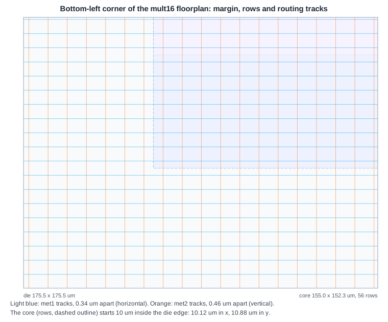
make_tracks creates a routing grid for every layer from the pitches in the technology LEF. In DEF:
TRACKS Y 170 DO 516 STEP 340 LAYER met1 ;
TRACKS X 230 DO 381 STEP 460 LAYER met2 ;
TRACKS Y 340 DO 258 STEP 680 LAYER met3 ;
TRACKS X 460 DO 191 STEP 920 LAYER met4 ;
TRACKS Y 1700 DO 51 STEP 3400 LAYER met5 ;
TRACKS Y 170 DO 516 STEP 340 LAYER met1 means: horizontal met1 tracks at y = 0.17 um, 0.51 um, 0.85 um and so on, 516 of them, 0.34 um apart, covering the whole die. Each layer also has tracks in its non-preferred direction (the DEF lists both), which the router uses only for short jogs. The detailed router puts wire centre lines on these tracks; the picture shows the met1 and met2 tracks at the corner of the multiplier's core.
Tracks cover the margin as well as the core. Wires to the pins run through the margin, and in a larger design power rings and long connections can use it too.
What the Core Margin Is For
- I/O pins of the block sit on the die edge, and their wires need a way into the core.
- Power rings around the core, on upper metal, can feed the straps from all four sides.
- Spacing to neighbours: when the block is placed in a chip, the margin keeps its cells away from the blocks next to it.
The lab uses a fixed 10 um margin. For the 8-bit counter that is a large share of the die (the core is 26 um wide in a 46 um die); for the multiplier it is a small one.
Quick Check
Q: How many met2 tracks cross one dfxtp_1 flip-flop, and why does that matter for routing?
Show Answer
The flip-flop is 7.36 um wide, so 7.36 / 0.46 = 16 vertical met2 tracks pass over it. Some are blocked by its pins and internal metal; the rest are available for wires passing over the cell. Dense areas of large cells leave fewer free tracks.
Running It in ChipVerify Lab
Run Place and Route on the multiplier, read the floorplan lines at the start of the OpenROAD log (the IFP messages) and compare the number of rows and sites with this article. In the layout viewer, zoom into a corner of the core to see where the rows start.
Common Mistakes
Mistake #1: Hand-picking a core that does not fit the grid
A core corner off the site or row grid is snapped, which changes the core size slightly. When the size matters, compute it in whole rows and sites.
Mistake #2: A margin too small for the pins
With many pins on one edge, the wires to them need space before they reach the cells. A very thin margin causes congestion along that edge.
Practice Exercise
Challenge: Count Rows and Sites
Run Place and Route on the multiplier at 30 % utilization. The log reports the core box. How many rows and sites per row does that give? Check your answer against the IFP-0001 message.
Hint
Rows = core height / 2.72 um; sites = core width / 0.46 um.
Solution
At 30 % the core runs from (10.12, 10.88) to (189.52, 187.68): 179.4 um wide and 176.8 um tall. That gives 176.8 / 2.72 = 65 rows and 179.4 / 0.46 = 390 sites per row.
Open the ready-made example in the lab, synthesize it and run Place and Route.
Summary
- The floorplan snaps the core to the site and row grid; the corner can move slightly.
- Rows hold the standard cells: core height / 2.72 um rows of core width / 0.46 um sites in sky130 hd.
make_trackslays a track grid for every layer from the LEF pitches, over the whole die.- The core margin holds the I/O pins and their wires, and power rings in larger designs.
