
There is more than one way to carry a clock across a chip. Symmetric H-trees, buffered trees built from clusters of flip-flops, meshes and spines all trade skew, power, wire and robustness differently. Standard-cell blocks almost always use a buffered tree, while large high-speed processors add meshes and spines on top. This article describes the four structures and then looks at the trees OpenROAD actually built for a 528-flop register file, with and without sink clustering.
7 min read | Intermediate
What You'll Learn
- Describe H-tree, buffered tree, mesh and spine clock structures
- Compare them in skew, power and wire
- Read the topology TritonCTS reports for a clock net
- Explain what sink clustering changes in a tree
Four Structures
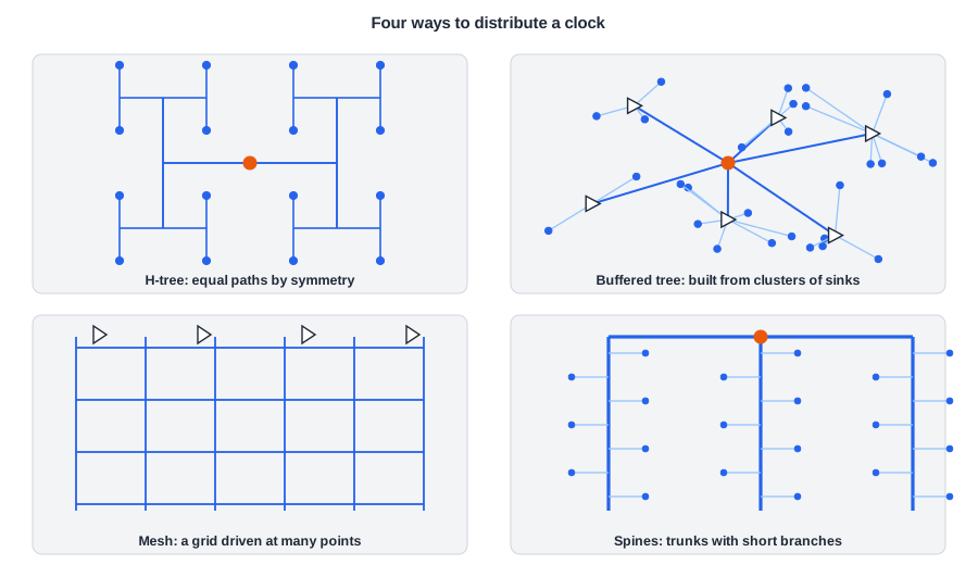
H-Tree
An H-tree splits the area into halves again and again, with the driver at the centre of each H. Every path from the root to a leaf has the same length and the same number of buffers, so the skew is zero by construction, provided the sinks sit exactly at the leaves. Real flip-flops are not placed on a regular grid, so a pure H-tree needs extra wire at the bottom to reach them, and that last stretch is where the skew comes back.
Buffered Tree
A buffered tree is built from the bottom up or with a top-down partition of the actual sink positions. Nearby flip-flops are grouped, each group gets a buffer, the buffers are grouped again, and so on up to the root. Branches are balanced by choosing buffer sizes and wire lengths, not by symmetry. It uses the least wire and power for a given skew target and is the standard approach in automatic CTS for standard-cell blocks.
Mesh
A clock mesh is a grid of wide metal wires driven at many points by a tree above it. Because the grid shorts all the drivers together, local differences in buffer delay average out, and the skew becomes very low and much less sensitive to variation. The cost is high: the grid's wire capacitance switches every cycle, and the parallel drivers fight each other briefly during each edge. Meshes are used for the highest-speed designs, where a few picoseconds of skew matter more than the extra power.
Spines
Spines are a few long, wide trunks across the block, driven from the middle, with short branches to the flip-flops nearby. They sit between a tree and a mesh: lower skew and better tolerance of variation than a tree, less wire than a full mesh. Fishbone structures and multi-source CTS are variations on the same idea.
| Structure | Skew | Sensitivity to variation | Power and wire | Typical use |
|---|---|---|---|---|
| H-tree | Low by symmetry | Medium | Medium | Top levels of a clock distribution |
| Buffered tree | Low, by balancing | Medium to high | Lowest | Standard-cell blocks, all automatic CTS |
| Mesh | Lowest | Lowest | Highest | High-speed processor cores |
| Spines | Low | Low | Medium to high | High-speed blocks |
Quick Check
Q: Why does a clock mesh tolerate variation in its buffers better than a tree does?
Show Answer
In a tree, each flip-flop is reached through one chain of buffers, so a slow buffer delays every flip-flop below it. In a mesh, many drivers are connected to the same grid, and each point of the grid is pulled by several of them. A slow driver is compensated by its neighbours.
What TritonCTS Builds
OpenROAD's clock tree tool, TritonCTS, combines the first two ideas: it lays out an H-tree topology over the region that contains the sinks, then connects the sinks at the bottom levels and inserts buffers. The log shows the topology level by level. For a register file with 528 flip-flops (32 registers of 16 bits, plus 16 output flip-flops):
[INFO CTS-0027] Generating H-Tree topology for net clk.
[INFO CTS-0028]  Total number of sinks: 528.
 Level 1
    Direction: Vertical
    Sinks per sub-region: 264
 Level 2
    Direction: Horizontal
    Sinks per sub-region: 132
 ...
 Level 6
    Direction: Horizontal
    Sinks per sub-region: 9
[INFO CTS-0032]  Stop criterion found. Max number of sinks is 15.
[INFO CTS-0018]     Created 81 clock buffers.
[INFO CTS-0012]     Minimum number of buffers in the clock path: 3.
[INFO CTS-0013]     Maximum number of buffers in the clock path: 3.
[INFO CTS-0016]     Fanout distribution for the current clock = 5:3, 6:6, 7:13, 8:15, 9:14, 10:8, 12:5..
The region is halved six times, alternating vertical and horizontal cuts, until each sub-region holds at most 15 sinks. Buffers are not placed at every level: the tree ended up with 81 buffers in three stages, 1 root, 16 in the middle and 64 at the leaves, and every flip-flop is behind exactly three of them. The fanout distribution says how many sinks each leaf buffer drives: 5 to 12, mostly 7 to 9.
Sink Clustering
With -sink_clustering_enable, TritonCTS first groups nearby flip-flops into clusters and puts one buffer at each cluster, then builds the tree over the cluster buffers instead of over the individual flip-flops:
clock_tree_synthesis -sink_clustering_enable \
                     -sink_clustering_size 10 \
                     -sink_clustering_max_diameter 50
Here each cluster holds up to 10 flip-flops within 50 um. The log reports the result:
[INFO CTS-0019]  Total number of sinks after clustering: 54.
[INFO CTS-0018]     Created 59 clock buffers.
[INFO CTS-0016]     Fanout distribution for the current clock = 3:1, 8:2, 9:1, 10:50, 12:1, 13:1, 14:1, 15:1..
[INFO CTS-0100]  Leaf buffers 54
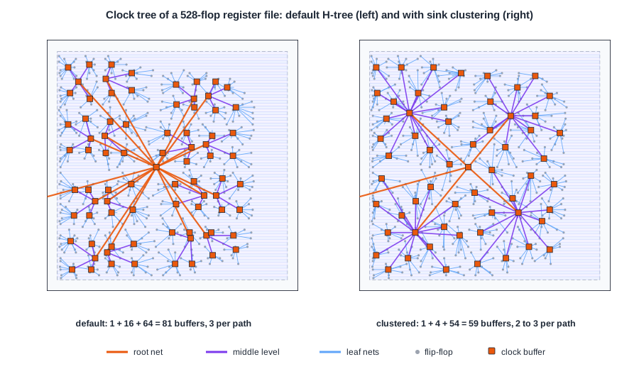
The picture shows both trees, with lines from every clock buffer to the cells it drives. On the left, the default tree: the root buffer in the middle feeds 16 middle buffers, and each of those feeds four leaf buffers. On the right, the clustered tree: the root feeds 4 middle buffers, and those feed the 54 cluster buffers, 50 of which drive exactly 10 flip-flops.
| Register file, 528 flip-flops | Default | Sink clustering |
|---|---|---|
| Clock buffers | 81 | 59 |
| Buffers per clock path | 3 | 2 to 3 |
| Skew after CTS | 0.02 ns | 0.02 ns |
| Latency | 0.63 to 0.65 ns | 0.64 to 0.66 ns |
| Routed clock wire | 5.95 mm | 6.16 mm |
| Clock network power | 1.77 mW | 1.74 mW |
| Worst hold slack after routing | 0.59 ns | 0.59 ns |
Clustering saved 22 buffers, more than a quarter, with the same skew and latency. The routed clock wire grew by 3.5 %, because the cluster buffers drive more flip-flops each, over longer local wires. The two effects nearly cancel in power: 1.7 % lower. On this small block the default tree was already good; clustering pays off more on large blocks, where the buffer count of the default tree grows quickly.
Quick Check
Q: Clustering reduced the buffer count by 27 % but the clock power by only 1.7 %. Where does most of the clock power go?
Show Answer
Into charging the clock wires and the flip-flops' clock pins, which are the same in both trees, plus the leaf buffers that drive them. Removing middle-level buffers saves only their own small share. The flip-flop load and the wire to reach it do not go away.
Running It in ChipVerify Lab
The lab's flow runs clock_tree_synthesis with its default options. Run Place and Route on a design with a few hundred flip-flops and find the CTS section of the log: the H-tree levels, the number of buffers created, the buffers per path and the fanout distribution. With PRO, the sink clustering option adds -sink_clustering_enable without a size or diameter, so TritonCTS sizes the clusters by the maximum capacitance a buffer may drive (CTS-0090 in the log). On the register file it made 45 clusters and 50 clock buffers instead of 81, and the clock network power fell from 2.55 to 1.75 mW. The register file needs more than the free tier's five minutes; with PRO it finishes in about five and a half.
Common Mistakes
Mistake #1: Judging a clock tree by its buffer count alone
Fewer buffers usually means more wire per buffer. In the register file, 22 fewer buffers saved only 1.7 % of clock power. Look at skew, wire, power and transition together.
Mistake #2: Expecting an H-tree to give zero skew in a placed block
The symmetry holds only down to the last level of the H. Flip-flops are not on the tree's grid, so the bottom connections differ in length and need balancing like any buffered tree.
Practice Exercise
Challenge: Levels of a Tree
A tree has a root buffer and every buffer drives at most 8 loads. What is the smallest number of buffer levels needed to reach 528 flip-flops? How many leaf buffers does that take at least?
Hint
Each level multiplies the number of reachable loads by up to 8.
Solution
One level reaches 8 flip-flops, two levels 64, three levels 512, four levels 4,096. So 528 flip-flops need four levels of buffers. The leaf level needs at least 528 / 8 = 66 buffers, which in turn need 9 buffers above them, then 2, then the root: about 78 buffers. TritonCTS built 81 in only three levels, because its root drives 16 middle buffers instead of 8.
Open the ready-made example in the lab, synthesize it and run Place and Route.
Summary
- H-trees balance by symmetry, buffered trees by sizing, meshes by shorting drivers together, spines by a few strong trunks.
- Automatic CTS for standard-cell blocks builds buffered trees; meshes and spines are for the fastest designs.
- TritonCTS lays out an H-tree topology over the sinks, stopping at 15 sinks per region by default.
- For 528 flip-flops it built 81 buffers in three stages with 0.02 ns skew.
- Sink clustering cut the tree to 59 buffers with the same skew and 1.7 % less clock power.
