
A power grid is built from three kinds of metal shapes. Rails run along every standard cell row and touch the power pins of the cells. Straps run across the core on the upper layers and feed the rails. A ring can surround the core or a macro and tie the straps together at the edges. This article describes each part, with the real numbers from the power grid of the 16x16 multiplier in sky130.
7 min read | Beginner
What You'll Learn
- Describe rails, straps, rings and via stacks and what each one does
- Explain why rails are on met1 and straps on the upper layers
- Read the pitch, width and offset of a strap pattern
- Decide when a core ring is worth adding
The Grid of the Multiplier
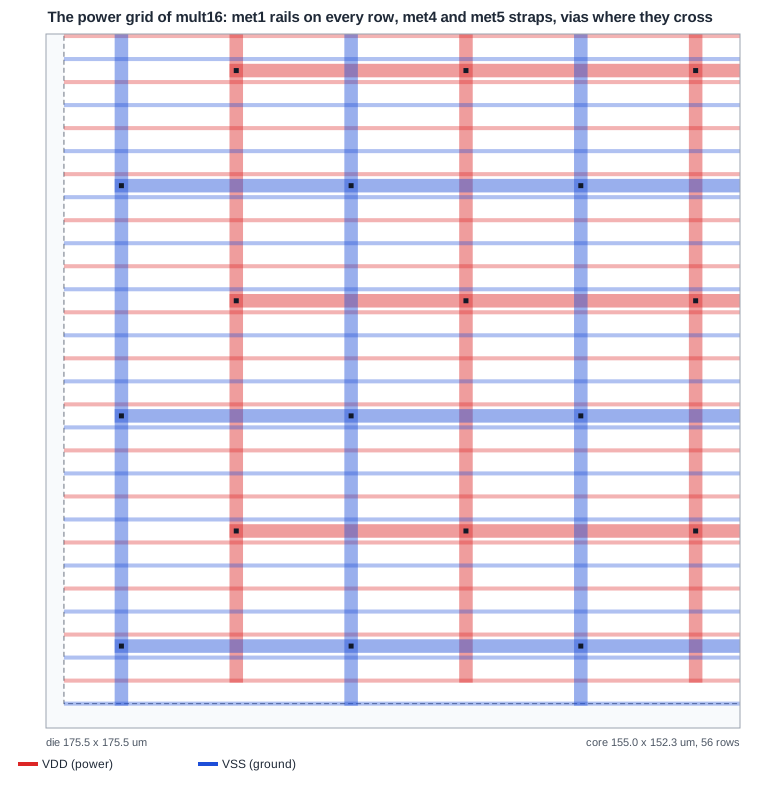
This is the bottom-left part of the multiplier's power grid. VDD is red, VSS is blue. Three layers carry power:
| Part | Layer | Direction | Width | Count in mult16 |
|---|---|---|---|---|
| Rails (follow-pins) | met1 | horizontal | 0.48 um | 28 VDD, 29 VSS |
| Straps | met4 | vertical | 1.60 um | 5 VDD, 6 VSS |
| Straps | met5 | horizontal | 1.60 um | 5 VDD, 6 VSS |
The core has 56 rows, so there are 57 rail positions: each rail between two rows is shared by both, because every second row is flipped. VDD and VSS alternate from row to row.
Rails
Every standard cell has its VPWR pin along its top edge and its VGND pin along its bottom edge (or the other way round in a flipped row), drawn on met1 across the full cell width. When cells sit side by side in a row, these pins join into one continuous line. The rail is a met1 wire laid exactly over that line, along the full row. That is why OpenROAD calls them follow-pins: they follow the cell pins.
Rails are thin, 0.48 um, the same width as the cell pins, and met1 has a sheet resistance of 0.125 ohm per square. A rail 155 um long has a resistance of about 0.125 x 155 / 0.48 = 40 ohm from end to end. Fed only from its ends, the cells in the middle would see a large drop. Rails therefore need to be fed often, along their length, from above.
Straps
Straps are wide wires on the upper layers that run across the core and connect to the rails at every crossing. In the multiplier:
- met4 straps run vertically, every 27.14 um for each net, 1.6 um wide. They cross every rail.
- met5 straps run horizontally, every 27.2 um, also 1.6 um wide, and connect to the met4 straps where they cross.
VDD and VSS straps alternate. The first VSS strap on met4 sits near x = 16.91 um and the first VDD strap at 30.48 um; the next ones follow at 44.05 and 57.62 um. Each net repeats every 27.14 um, and the two nets are 13.57 um apart, half a pitch.
The upper layers are used because they are thicker. met4 has 0.047 ohm per square, less than half of met1, and met5 has 0.0285. A 1.6 um wide met4 strap 150 um long has about 4.4 ohm, against 40 ohm for a met1 rail of the same length.
Quick Check
Q: Why do the met4 straps run vertically while the rails run horizontally?
Show Answer
A strap must cross the rails to feed them. Vertical met4 straps cross every horizontal rail, so each crossing gets a via stack. It also matches the preferred direction of met4 in sky130, which is vertical.
Via Stacks
A met4 strap cannot touch a met1 rail directly. At each crossing, a stack of vias connects met1 to met2 (via), met2 to met3 (via2) and met3 to met4 (via3). In the multiplier there is one stack wherever a strap crosses a rail of the same net: 28 VDD rails times 5 VDD straps gives 140 stacks for VDD, and 29 times 6 gives 174 for VSS.
Vias are resistors too, and each one may only carry a limited current. A stack is usually an array of several vias side by side, sized to the width of the rail. Electromigration shows the current through these stacks.
Rings
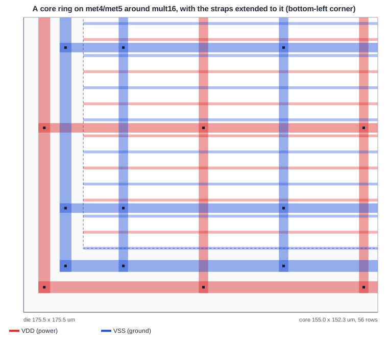
A ring is a pair of wide wires, one VDD and one VSS, around the core, on two layers: here met4 for the vertical sides and met5 for the horizontal ones, each 2.0 um wide. The straps are extended to the ring, so every strap is tied to its neighbours at both ends.
A ring is useful when power enters at the edge of the block: in a wire-bonded chip, where the supply pads sit around the die, or for a block inside a larger chip that is fed from the sides. It also gives a convenient place to connect macros and the grid of the surrounding chip.
For the multiplier, adding the ring changed the worst static IR drop from 1.31 mV to 1.33 mV, practically nothing. The analysis feeds power into the top layer of the grid across the whole core, as a flip-chip package would, so the current never has to pass through the ring. Whether a ring helps depends on where the power comes from.
Quick Check
Q: A block is placed in the middle of a large chip. The chip's top-level grid runs met5 straps right over the block. Does the block need its own ring?
Show Answer
Not for power delivery: the block's straps can connect directly to the chip's straps above it. A ring may still be added to make the block's power connection easy to find and check, but it is not what keeps the drop low.
Pitch, Width and Offset
Three numbers define a set of straps:
- Width: wider straps have less resistance and carry more current, but take more routing tracks.
- Pitch: the distance between straps of the same net. A smaller pitch means the rails are fed more often, so the drop is lower.
- Offset: where the first strap sits, measured from the core edge. It is usually chosen so that the straps do not land on the edge itself.
Every strap takes routing resources from the signals. A 1.6 um met4 strap, with its spacing, blocks two to three met4 tracks (pitch 0.92 um), so the VDD and VSS straps together take about 5 of the 29 tracks in every 27 um, close to 17 % of met4. The power grid designer looks for the lowest strap density that still meets the IR drop and electromigration targets. IR Drop: Static and Dynamic measures how the pitch and width change the drop.
Running It in ChipVerify Lab
Run Place and Route on the multiplier and read the PDN messages in the log, then open the layout and switch on only met1, met4 and met5. Compare what you see with the table above: are there straps on met4 and met5, or only rails? At the time of writing the lab's default script builds the met1 rails only; with PRO you can add the strap commands from Building a PDN in OpenROAD to a custom script.
Common Mistakes
Mistake #1: Thinking rails alone are enough
Rails are thin met1 wires with tens of ohms along a row. Without straps feeding them at regular intervals, cells far from the feed points see a large drop.
Mistake #2: Adding a ring and expecting a lower drop everywhere
A ring only helps if current enters at the edges. With power fed from the top layer across the core, the straps and their pitch matter much more.
Mistake #3: Straps in the wrong direction for their layer
A strap against the preferred direction of its layer blocks many signal tracks and does not cross the layer below. Run straps in the preferred direction: met4 vertical, met5 horizontal in sky130.
Practice Exercise
Challenge: Strap Resistance
Compute the resistance of one met5 strap across the multiplier's core (155 um, 1.6 um wide) and compare it with one met1 rail of the same length. How many met1 rails in parallel would match one met5 strap?
Hint
R = sheet resistance x length / width. Sheet resistance: met1 0.125, met5 0.0285 ohm per square.
Solution
met5: 0.0285 x 155 / 1.6 = 2.8 ohm. met1: 0.125 x 155 / 0.48 = 40.4 ohm. About 15 rails in parallel would match one met5 strap, which is why the straps carry the current across the core and the rails only the last few microns to the cells.
Open the ready-made example in the lab, synthesize it and run Place and Route.
Summary
- Rails (follow-pins) on met1 run along every row and touch the cells' power pins.
- Straps on thick upper layers (met4 vertical, met5 horizontal in sky130) cross the core and feed the rails through via stacks.
- In the multiplier: 0.48 um rails, 1.6 um straps every 27 um per net, VDD and VSS alternating half a pitch apart.
- A ring ties the straps together at the core edge; it matters when power enters from the sides.
- Pitch, width and offset trade IR drop against routing tracks.
