
Most chips are not purely digital. A data converter, a PLL, a power-on reset, a bandgap reference or a temperature sensor sits among the standard cells, built by analog designers as a hard macro. These blocks work with small voltages and are disturbed by exactly what digital logic produces in abundance: switching noise on the supplies and in the substrate. Placing and connecting them is the physical designer's job, and the floorplan decides how quiet their environment is. This article covers the noise paths, the isolation techniques, and the rules for integrating an analog macro into a digital chip.
7 min read | Advanced
What You'll Learn
- Describe how digital noise reaches analog circuits
- Explain guard rings, deep n-wells and separate supplies
- Plan the placement and routing around an analog macro
- List the checks specific to mixed-signal integration
How Digital Noise Reaches Analog Circuits
Thousands of gates switching on a clock edge produce current spikes. They reach a sensitive analog block through three paths:
- Shared supplies. Digital current through the supply's resistance and inductance moves the supply voltage, the IR drop and ground bounce of Power and Ground Pads: How Many and Where. An analog block on the same supply sees all of it.
- The substrate. The body terminal of every bulk transistor connects to the substrate or a well through a relatively resistive contact. Current injected into the substrate, by capacitive coupling through junctions or by impact ionization, moves the local body voltage, and through the body effect the threshold voltages of nearby transistors. In a mixed-signal chip, the noise of the digital ground travels to the analog circuits through the shared substrate.
- Coupling between wires. A digital wire running next to or over an analog net couples into it through their capacitance, as in Crosstalk, Shielding and Non-Default Rules.
Isolation Techniques
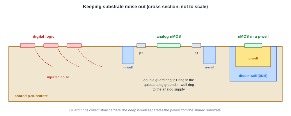
The standard advice is to separate analog circuits physically from digital ones and protecting them with guard rings connected to a quiet analog supply:
- Guard rings. Continuous rings of substrate or well contacts around the circuit to protect. A p+ ring tied to the quiet ground collects stray carriers in the substrate before they reach the transistors inside; an n-well ring tied to a supply adds a second barrier. Double guard rings are the conservative choice, the same structure recommended around I/O output transistors against latch-up.
- Plenty of substrate contacts in both digital and analog areas, giving the substrate a low-resistance path to its supply so injected current does not build up voltage.
- Triple wells. Twin-tub or triple-well processes and SOI experience much less substrate coupling because transistors sit in their own wells. sky130 has a deep n-well layer, DNM in its mask list from From GDSII to Masks, which places a p-well with its nMOS transistors inside an n-type tub, separated from the shared substrate.
- Separate supplies. Analog blocks get their own supply and ground pads, ring buses and grid, as Caravel does with its vdda and vssa supplies for analog circuits, separate from the 1.8 V digital ones.
Quick Check
Q: An analog block has its own supply pads, but its guard ring is tied to the digital ground because that net is closer. What has gone wrong?
Show Answer
The guard ring now injects the digital ground's noise straight into the substrate around the analog transistors, the opposite of its purpose. A guard ring must connect to a quiet supply, normally the analog ground, so that it collects noise instead of delivering it.
Floorplanning an Analog Macro
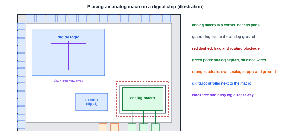
- Distance. Put the analog block at the edge of the core, often in a corner, near its own pads and as far as practical from the noisiest digital logic: clock drivers, wide buses, high-activity datapaths.
- Keep-out band. A halo around the macro, from Macro Placement: Halos and Channels, keeps standard cells away and leaves room for the guard rings.
- Routing blockages. Digital routes must not cross over the macro on the layers it uses or on the layers just above its sensitive nodes; the macro's LEF usually declares obstructions, and the floorplan adds blockages from Placement Blockages and Keep-Out Regions where it does not.
- Clock tree. Keep clock buffers and clock wires away; they switch every cycle at full strength.
- Analog pads. Analog pads connect directly to the analog circuits without digital buffers, and that their ESD protection is kept small so it does not limit bandwidth. Place them next to the macro so the analog signal wires are short.
The sky130 GPIO cell, from I/O Cells: Drivers, Receivers and Level Shifting, shows another option: it has two analog buses, AMUXBUS_A and AMUXBUS_B, that run through the pad ring, and analog pins that connect the pad to them. An analog signal can travel along the ring to the pad that needs it instead of crossing the digital core.
Routing Analog Signals
- Shielding. Sensitive analog nets get ground shields on both sides, and sometimes above and below, using the non-default rules and shielding of the crosstalk article.
- Width and resistance. Reference currents and sense lines are routed wide, because their resistance matters and their currents may be small but must be precise.
- Symmetry. Differential signals are routed as matched pairs, side by side, with the same length and the same neighbours.
- Fill. Metal fill changes the capacitance of nearby wires. Analog blocks often have fill exclusion areas or require a uniform, symmetric fill pattern, coordinated with Filler Cells, Metal Fill and Density Rules.
Quick Check
Q: Why do a differential pair's two wires need the same neighbours, not just the same length?
Show Answer
Coupled noise appears on each wire according to its neighbours. If both wires see the same aggressors equally, the noise is common to both and a differential receiver rejects it. Different neighbours couple different noise into each wire, which appears as a differential error.
Boundaries Between Analog and Digital
Every signal between the analog and digital domains crosses a supply boundary. Digital control bits going into an analog block may need level shifting, as in Multi-Voltage Implementation, and a buffer powered by the analog supply at the input so the digital edge does not inject noise directly. Outputs from the analog side, such as comparator results, are synchronized in the digital domain, and their timing is constrained at the macro boundary with the macro's own timing model. The ESD checks of ESD Protection for Physical Designers also apply: every crossing between separate grounds needs a discharge path.
Checks Specific to Mixed-Signal Chips
- LVS with the analog devices, including resistors, capacitors and devices in deep n-well, which need the right rule deck options.
- Guard ring continuity and connection to the intended quiet supplies.
- No digital routing over the analog macro's restricted area.
- Correct supplies for every cell at the boundary.
- Simulation of the analog block with the extracted parasitics of the real layout around it, which the analog designers usually run.
Running It in ChipVerify Lab
At the time of writing, the lab's flow is digital only: it places standard cells and the SRAM macro of Macro Placement: Halos and Channels, but has no analog macros, guard rings or separate supplies. The halo and blockage techniques of that article are the same ones used to protect an analog macro. The sky130 details come from the PDK and Caravel design files.
Common Mistakes
Mistake #1: Sharing the analog supply with digital logic
Digital switching noise then reaches the analog block directly. Give analog circuits their own supply and ground.
Mistake #2: Routing digital buses over an analog macro
The coupling lands right on the sensitive nodes. Block the macro's area for digital routing.
Mistake #3: Placing the analog block in the middle of the core
It is then surrounded by digital noise and far from its pads. Place it at the edge, near its analog pads.
Practice Exercise
Challenge: Plan the Corner
A chip has a 12-bit data converter macro, three analog pads, a digital controller that talks to the converter over 14 control and data signals, and a large clock tree. List five floorplan and routing decisions for the converter's corner.
Hint
Think of distance, supplies, pads, routing and the boundary signals.
Solution
(1) Place the converter in a core corner next to its three analog pads. (2) Give it separate analog supply and ground pads with their own ring and guard rings tied to the analog ground. (3) Add a halo and a routing blockage over the macro, and keep the clock tree out of the corner. (4) Place the digital controller next to the converter on the digital side so the 14 boundary signals are short, with level shifters or analog-supplied input buffers if the supplies differ. (5) Shield the analog signals from the pads to the converter and coordinate the fill around it.
Summary
- Digital noise reaches analog circuits through shared supplies, the substrate and wire coupling.
- Guard rings tied to a quiet supply, many substrate contacts and deep n-wells limit substrate noise.
- Analog blocks get their own supplies and pads, as Caravel's vdda and vssa supplies show.
- Place analog macros at the edge near their pads, with halos, routing blockages and no clock tree nearby.
- Analog signals are shielded, routed symmetrically and given controlled fill; every boundary signal needs supply and ESD checks.
