
Standard cells are the building blocks of a digital layout: small, pre-designed layouts of gates and flip-flops that all share one height. Because they share a height, they can be lined up in rows like books on a shelf, with power and ground running along the top and bottom of every row. This article explains standard cells, placement sites and rows using the sky130 high-density library, and shows how rows alternate so that neighbouring rows share a power rail.
7 min read | Beginner
What You'll Learn
- Describe what a standard cell is and what all cells in a library have in common
- Explain placement sites and why cell widths are whole numbers of sites
- Read a ROW statement in a DEF file
- Explain why rows alternate orientation and share power rails
Standard Cells
A standard cell library holds a few hundred cells: inverters, NAND and NOR gates, AND-OR-INVERT gates, multiplexers, adders, flip-flops and latches, each in several drive strengths. The sky130 high-density library, sky130_fd_sc_hd, has 437 cells in its LEF. The suffix is the drive strength: inv_1 is the smallest inverter, inv_16 drives sixteen times the current.
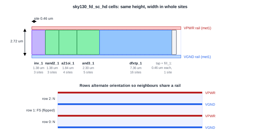
All cells in the library follow the same template:
- Same height: 2.72 um for every
sky130_fd_sc_hdcell, eight times the 0.34 um met1 track pitch. Libraries are often described by their height in tracks; taller cells have more room for transistors and are faster but larger. - Width in whole sites: the site of this library,
unithd, is 0.46 um wide. Aninv_1is 3 sites (1.38 um), anand3_15 sites (2.30 um), adfxtp_1flip-flop 16 sites (7.36 um). - Power on the edges: the power pin
VPWRruns along the top edge on met1, the ground pinVGNDalong the bottom edge. When cells are placed side by side, these rails join into one continuous wire. - Well connections: in the Liberty and netlist views, sky130 cells also have
VPBandVNBpins for the n-well and p-well (the transistor bodies). The cells do not tap their wells to the supplies themselves; separate tap cells do that. The LEF abstract used for placement leaves these two pins out.
Quick Check
Q: A buf_16 is 10.12 um wide. How many sites is that?
Show Answer
10.12 / 0.46 = 22 sites. Every cell width in the library divides evenly by the site width, so cells can be placed next to each other without gaps.
Sites and Rows
A site is the smallest legal placement unit: one site wide and one cell high. A row is a line of sites across the core. The floorplan step creates the rows, and the placer may only put a cell so that it starts on a site boundary inside a row. In DEF, a row looks like this:
ROW ROW_0 unithd 10120 10880 N DO 57 BY 1 STEP 460 0 ;
ROW ROW_1 unithd 10120 13600 FS DO 57 BY 1 STEP 460 0 ;
Row 0 starts at (10.12 um, 10.88 um), has 57 sites of type unithd, one site every 0.46 um, so it is 26.22 um long. Row 1 starts 2.72 um higher, exactly one cell height.
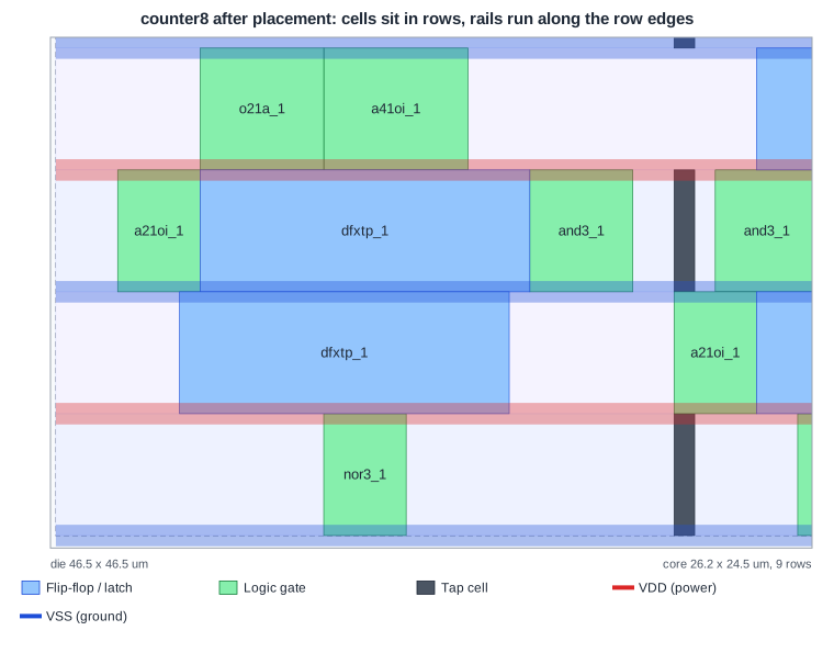
This is the placed counter, zoomed in. Every cell sits in a row; the flip-flops (blue) take 16 sites, the gates (green) 3 to 8. The thin red and blue bands are the met1 rails along the row edges, and the dark grey cells are tap cells.
Why Rows Alternate
Look at the orientation in the DEF: row 0 is N (north, upright), row 1 is FS (flipped south, mirrored upside down). Flipping every other row means that the bottom edge of row 1 has the same supply as the top edge of row 0. In the counter, row 0 has VGND at the bottom and VPWR at the top; row 1, flipped, has VPWR at the bottom, sharing the VPWR rail with row 0, and VGND at the top, sharing it with row 2.
Sharing rails saves area: one rail serves two rows. It also means a cell placed in a flipped row is mirrored, which the placer handles automatically: a cell in an FS row gets orientation FS, like flip-flop _47_ in the counter: PLACED ( 12880 13600 ) FS.
Quick Check
Q: The counter's core has 9 rows of 57 sites. How many dfxtp_1 flip-flops could one row hold at most?
Show Answer
57 / 16 = 3.56, so three flip-flops (48 sites), with 9 sites left. In practice the placer also needs room for logic and tap cells, which is why the core is never filled completely.
Physical-Only Cells
Some cells in the library have no logic function and exist only for the layout:
- Tap cells (
tapvpwrvgnd_1, 1 site): connect the wells to VPWR and VGND, at regular distances, to prevent latch-up. - Filler cells (
fill_1tofill_8): fill empty sites so the wells and rails are continuous. - Decap cells (
decap_3and up): small capacitors between VPWR and VGND that steady the local supply. - Diodes (
diode_2): protect gates from the antenna effect during manufacturing.
They are covered in Tap Cells, Endcaps, Latch-Up and Decaps and The Antenna Effect.
Running It in ChipVerify Lab
Run Place and Route on the counter and open the layout viewer. Zoom in on the rows and find a flip-flop, a gate, a tap cell and the fillers between them. The Area and Floorplan section of the report gives the core size and the utilization.
Common Mistakes
Mistake #1: Mixing libraries of different heights in one row
A row has one site type. Cells of a library with another height (sky130 also has hs, ms and ls libraries with 3.33 um cells) cannot share it. Mixed-height designs need separate row regions.
Mistake #2: Forgetting the well connections
Because sky130 cells do not tie their wells internally, a layout without tap cells has floating wells. That is a latch-up risk and a DRC or LVS failure.
Practice Exercise
Challenge: Fill a Row
One row of the counter's core is 57 sites long. How many inv_1 cells would fit in one row? If a row holds two dfxtp_1 flip-flops and one tap cell, how many sites are left for logic? Then check the real counter in the lab: how many flip-flops does the fullest row hold?
Hint
An inv_1 is 3 sites, a dfxtp_1 16 sites, a tap cell 1 site.
Solution
57 / 3 = 19 inverters. Two flip-flops and a tap take 33 sites, leaving 24 sites for logic. In the placed counter no row holds more than two flip-flops: at 50 % target density the placer spreads the cells over all nine rows.
Open the ready-made example in the lab, synthesize it and run Place and Route.
Summary
- Standard cells share one height (2.72 um in
sky130_fd_sc_hd) and have widths in whole sites of 0.46 um. - VPWR runs along the top and VGND along the bottom of every cell on met1; placed side by side they form continuous rails.
- Rows are lines of sites; every other row is flipped so that neighbouring rows share a rail.
- Tap, filler, decap and diode cells are physical-only cells added during layout.
