
Power gating turns off the supply of a block while it is idle, so it stops leaking. A row of switch transistors sits between the always-on supply and a "virtual" supply that feeds the block's cells; opening the switches removes nearly all of the block's leakage. It is the easiest way to reduce static power during sleep. It is also one of the most layout-heavy low-power techniques: the switches, the always-on control network, the isolation cells, the retention registers and the rush of current at power-up are all physical design problems. This article covers each, with the sky130 cells that implement them.
8 min read | Advanced
What You'll Learn
- Describe a power-gated domain: switches, virtual supply, isolation and retention
- Size a power switch for a voltage droop target
- Explain rush current and how switch control networks limit it
- Read OpenROAD's power switch options and the sky130 low-power cells
The Parts of a Gated Domain
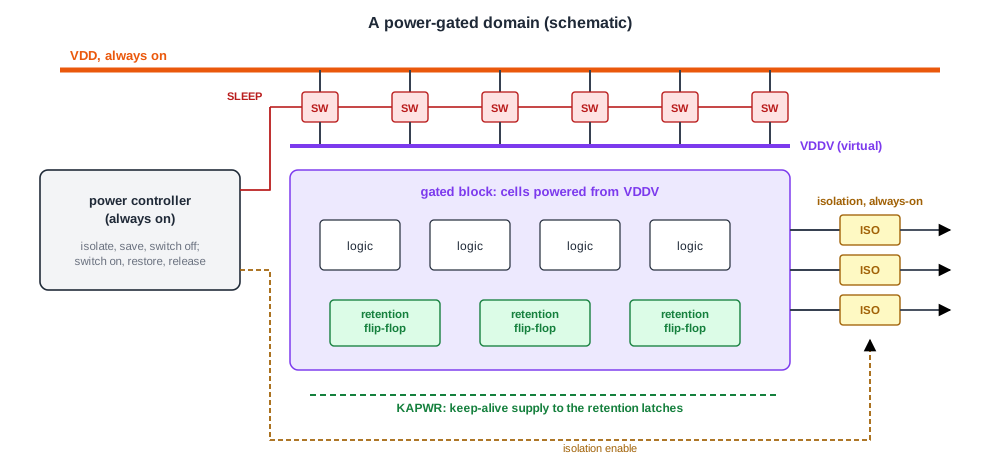
The basic arrangement:
- Switches. High-threshold transistors between the real supply and the block's virtual supply. pMOS switches in the supply are called headers, nMOS switches in the ground footers. Footers deliver more current per width, but many projects choose headers because a constant ground is simpler for designers and tools, especially with several supplies.
- Isolation. When the block is off, its virtual supply sinks toward zero and its outputs float through the forbidden zone between 0 and 1. Isolation cells on every output force a valid value so the logic that stays on is not confused.
- State. The block's registers lose their contents. Either the state is reset on power-up, saved to memory first, or kept in retention registers that have a small part powered by a separate always-on supply.
- Control. An always-on power controller sequences the steps: isolate, save, switch off; and on wake-up switch on, wait, restore, release isolation.
The UPF tutorial covers how this is described as power intent, in UPF Power Shutoff, UPF Isolation Strategies and UPF Retention Strategies. This article is about building it.
The sky130 Low-Power Cells
The sky130 libraries include cells for each part. Their descriptions, from the library's cell definitions:
| Cell | Library | Description |
|---|---|---|
| sleep_sergate_plv | sky130_fd_sc_lp | connects VPWR to VIRTPWR when not in sleep mode: a header switch |
| srsdfrtp | sky130_fd_sc_lp | scan flop with sleep mode, with a KAPWR keep-alive supply pin: a retention flip-flop |
| lpflow_isobufsrc | sky130_fd_sc_hd | input isolation, non-inverted sleep |
| lpflow_inputiso0p, lpflow_inputiso1p | sky130_fd_sc_hd | input isolators that clamp to 0 or to 1 |
| lpflow_clkbufkapwr, lpflow_decapkapwr | sky130_fd_sc_hd | clock buffer and decap on the keep-alive rail |
| lpflow_bleeder | sky130_fd_sc_hd | current bleeder, a weak pull-down to ground |
The KAPWR pin is the keep-alive supply: it stays on when the cell's main supply is gated, which is what lets a retention flop keep its state and a keep-alive clock buffer drive it. These cells have extra supply pins that ordinary placement and routing do not handle, which is why the lab's flow excludes all lpflow cells from synthesis and placement with a dont-use list.
Sizing the Switches
A switch has resistance, so the virtual supply droops a little below the real one when the block draws current, and the block slows down. The switch is usually sized for a delay increase of 5 to 10 %, using the block's average current. A classic example: a cache in a 65 nm process at 1 V draws 2 W, so 2 A. A 5 % droop allows 0.05 V / 2 A = 25 milliohms. With a pMOS on-resistance of 2 kilohm-micrometres, the switch must be 2,000 / 0.025 = 80,000 um wide; their circuit simulation shows that 37,000 um is enough, because the on-resistance at a low drain-source voltage is lower than the estimate.
Tens of thousands of micrometres of switch are not one transistor. They are hundreds or thousands of switch cells spread over the domain, each feeding the virtual rail around it, so that no cell is far from a switch. Their total width sets the droop; their spacing sets the IR drop along the virtual rail, which IR Drop: Static and Dynamic analyses like any other grid.
Quick Check
Q: Wider switches reduce the droop. Why not make them as wide as possible?
Show Answer
The switches leak when they are off, and that leakage is what remains of the block's power during sleep. Wider switches also take more area and more energy to turn on and off. The width is a trade-off between active-mode slowdown and sleep-mode leakage.
Rush Current
When the switches close, the virtual supply and all the capacitance on it charge up from zero. This inrush current can cause IR and L dI/dt noise on the shared supply and electromigration in the power bus. Its size depends on how fast the switches turn on. With 2 nF of capacitance on the virtual supply, charged from 0 to 1 V, the average current during the turn-on is:
| Turn-on time | Average current |
|---|---|
| 1 ns | 2 A |
| 10 ns | 0.2 A |
| 100 ns | 20 mA |
| 1 us | 2 mA |
The capacitance is an assumption for the example; the trend is not. Turning everything on at once draws amperes from a supply that the neighbouring, still-running blocks share, which can make them fail. The cure is to turn the switch on gradually by controlling how many parallel transistors are on.
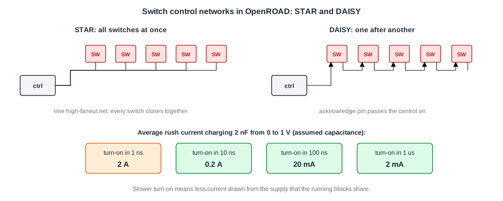
OpenROAD's power grid generator supports two control networks for the switches it inserts: STAR, where the control signal drives every switch as one high-fanout net, and DAISY, where the switches are chained, each passing the control on through an acknowledge pin. A daisy chain turns the domain on over the chain's delay instead of all at once. Real designs often use two chains: a few weak switches first to charge the rail slowly, then the strong ones.
Power Switches in OpenROAD
The power grid generator, from Building a PDN in OpenROAD, inserts switches where the standard cell rails of a switched domain connect to the mesh above them. The mesh stays on the always-on supply; the rails become the virtual supply. From its documentation:
define_power_switch_cell -name POWER_SWITCH -control SLEEP \
    -power_switchable VDD -power VDDG -ground VSS
define_pdn_grid -name sw_grid -voltage_domains SW_DOMAIN \
    -power_switch_cell POWER_SWITCH -power_control nPSO \
    -power_control_network DAISY
-poweris the switch pin on the unswitched supply,-power_switchableits output, the virtual supply.-acknowledgenames the output pin a daisy chain needs.- The domain itself comes from the power intent, read with
read_upfas in Multi-Voltage Implementation.
Layout Rules for a Gated Domain
- Always-on routing. The switch control, the isolation enables, the retention controls and the keep-alive supply must be powered and buffered by always-on cells, even where they run through the gated area. Buffers on these nets need an always-on supply, so they are special cells or sit in always-on islands.
- Isolation cell placement. Isolation cells sit at the domain boundary, powered by the receiving, always-on side, so they keep working when the source is off.
- Retention supply. The keep-alive rail reaches every retention register, adding a supply net to route in the gated area.
- IR drop in two modes. Check the drop across the switches and along the virtual rails at full activity, and the noise on the shared supply during wake-up.
- Sequencing in timing. The wake-up time, from the control's edge to a stable virtual supply, is a design parameter that the power controller must wait for.
Quick Check
Q: An isolation cell is placed inside the gated domain and powered by the virtual supply. What goes wrong when the domain is switched off?
Show Answer
The isolation cell loses its own supply together with the block it is meant to isolate, so its output floats too, and the always-on logic sees the very undefined value the cell was supposed to prevent. Isolation cells must be powered by the always-on side.
Running It in ChipVerify Lab
At the time of writing, the lab's flow is single-domain and excludes the sky130 low-power cells, so power gating cannot be built there. The cell descriptions come from the sky130 library definitions, the OpenROAD commands from its documentation, and the switch sizing example is a classic 65 nm case.
Common Mistakes
Mistake #1: Turning all switches on at once
The rush current disturbs the blocks that are still running. Stage the turn-on with a daisy chain or weak switches first.
Mistake #2: Powering control buffers from the gated supply
Every buffer on a switch control, isolation enable or retention control must stay on. Use always-on cells.
Mistake #3: Sizing switches for the average current only
The average sets the steady droop; dynamic peaks and wake-up need a separate check.
Practice Exercise
Challenge: Size a Header
A block at 1.8 V draws 0.36 A on average. The droop may be at most 3 %. The header transistors have an on-resistance of 3 kilohm-micrometres. Estimate the total switch width, and the number of switch cells if each is 50 um wide.
Hint
Allowed resistance = allowed droop / current; width = on-resistance per micrometre / allowed resistance.
Solution
Droop 0.03 x 1.8 = 0.054 V; resistance 0.054 / 0.36 = 0.15 ohm; width 3,000 / 0.15 = 20,000 um, which is 400 cells of 50 um. As the 2 A example shows, simulation usually allows somewhat less, since the on-resistance at low drain voltage is lower than this estimate.
Summary
- Power gating places switches between the always-on supply and a virtual supply, and needs isolation, state retention and an always-on controller.
- sky130 has a header switch and retention flops in its lp library and isolation and keep-alive cells in hd.
- Switches are sized for a droop of a few percent at the average current; a 2 A example needs tens of thousands of micrometres.
- Rush current at wake-up is limited by staging the switches, for example with OpenROAD's DAISY control network.
- Control, isolation and retention nets stay on always-on supplies; isolation cells are powered by the receiving side.
