
Some cells in a layout do no logic at all. Tap cells tie the wells and the substrate to the supplies so that the chip cannot latch up. Endcaps close off the ends of the rows. Decap cells add capacitance between VDD and VSS to steady the supply. This article explains each of them, why latch-up makes tap cells necessary, and shows the tap cells and decaps in the 16x16 multiplier.
8 min read | Intermediate
What You'll Learn
- Explain latch-up and how tap cells prevent it
- Insert tap cells in OpenROAD and read their pattern
- Describe what endcap cells are for
- Fill empty sites with decap cells instead of plain fillers
Latch-Up
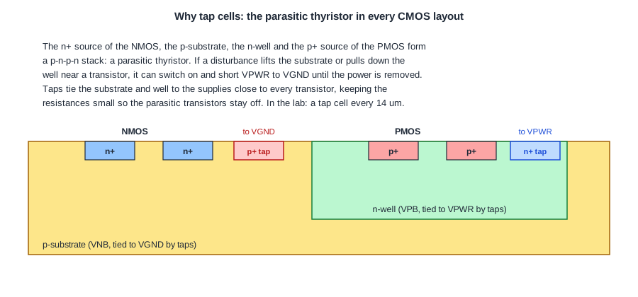
Every CMOS gate sits on a p-substrate with an n-well for its PMOS transistors. The n+ source of an NMOS, the p-substrate, the n-well and the p+ source of a PMOS form a p-n-p-n stack. That stack is a parasitic thyristor: two bipolar transistors, a PNP and an NPN, each feeding the other's base.
Normally both are off. But if a disturbance, such as a current spike, an I/O pin driven past the supply, or a particle hit, pushes current into the substrate or the well, the voltage drop across their resistance can switch one transistor on. It then turns on the other, and the pair holds itself on: a low-resistance path from VDD to VSS that stays until the power is removed. That is latch-up. It can destroy the chip with the heat.
The defence is to keep the well and substrate resistances small, so that no current can build up enough voltage to turn the parasitic transistors on. That means tying the n-well to VDD and the p-substrate to VSS at many points, close to every transistor.
Tap Cells
Many libraries, including sky130 hd, have no well or substrate contacts inside the logic cells, to keep them small. The contacts are in separate cells: sky130_fd_sc_hd__tapvpwrvgnd_1, one site wide, with an n+ tap in the well to VPWR and a p+ tap in the substrate to VGND. The foundry rule says how far any transistor may be from a tap.
tapcell -tapcell_master sky130_fd_sc_hd__tapvpwrvgnd_1 -distance 14
tapcell places tap cells in every row so that no point is more than the given distance from one. It runs right after the floorplan, before the standard cells are placed, and the placer then works around them. For the multiplier:
[INFO TAP-0005] Inserted 319 tapcells.
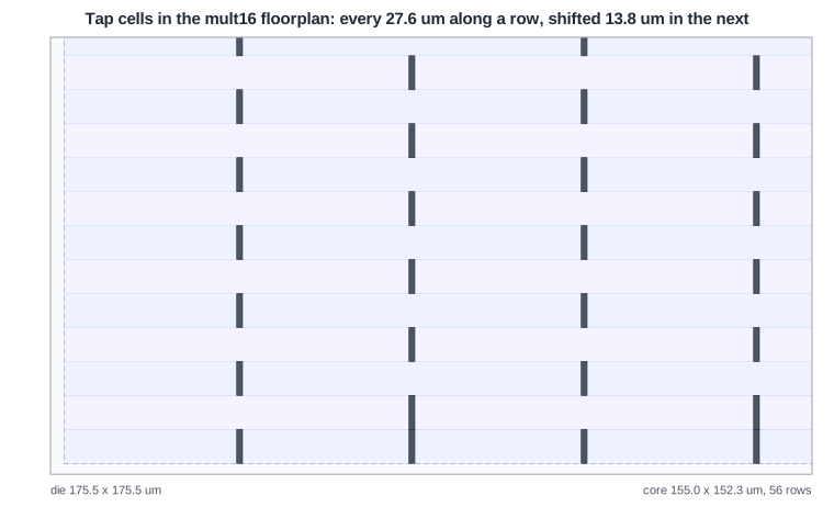
The taps form a checkerboard. Within a row they repeat every 27.6 um, and the next row's taps are shifted by 13.8 um. A tap reaches its own row and the rows above and below, because neighbouring rows share their well or substrate, so with the stagger no point is more than about 14 um from a tap. The bottom and top rows have a neighbour on one side only, so they get taps every 13.8 um. The 319 taps take about 400 um2, under 4 % of the cell area.
Quick Check
Q: Why are the tap cells inserted before placement and not after?
Show Answer
They must sit at fixed intervals in every row. After placement the rows are full of cells and there may be no free site at the required spot. Placing them first lets the placer treat them as fixed obstacles.
Endcaps
An endcap (boundary) cell sits at each end of every row and around macros. In many processes the well and implant layers need a defined edge, and the last cell of a row would otherwise end with a layout that breaks a spacing or density rule. The endcap provides a clean, rule-correct boundary, and in some libraries it also carries a tap.
The sky130 hd library has no cells of class ENDCAP, and the lab's flow inserts none; the row ends are covered by tap and filler cells. In other libraries, tapcell takes an -endcap_master option and inserts both in one step.
Decap Cells
A decap cell is a capacitor between VDD and VSS, built from the gate capacitance of transistors. When nearby cells switch and draw a sudden current, the decap supplies part of it from its stored charge, so less of the peak has to travel through the grid. That reduces the dynamic IR drop and the supply noise; it does nothing for the static drop, which depends on the average current.
The cheapest place for decaps is the empty sites left after placement and routing, which are otherwise filled with filler cells. Listing the decap cells first in the filler command fills the gaps with decaps wherever they fit, and with plain fillers where only narrow gaps remain:
filler_placement {sky130_fd_sc_hd__decap_12 sky130_fd_sc_hd__decap_8 sky130_fd_sc_hd__decap_6 sky130_fd_sc_hd__decap_4 sky130_fd_sc_hd__decap_3 sky130_fd_sc_hd__fill_1 sky130_fd_sc_hd__fill_2}
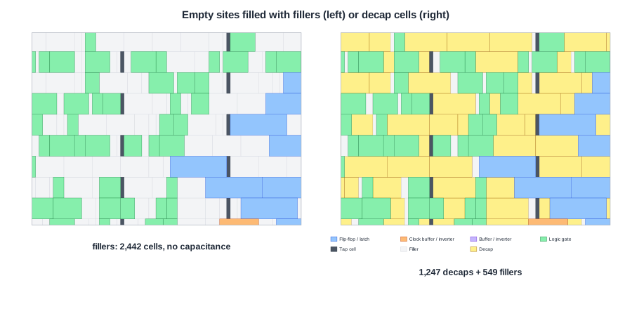
For the multiplier:
| Fill | Cells added | Reported utilization | Worst static IR drop |
|---|---|---|---|
| fillers only (lab default) | 2,442 fillers | 44 % | 1.31 mV |
| decaps first | 1,247 decaps (458 decap_12, 264 decap_8, 184 decap_6, 169 decap_4, 172 decap_3) + 549 fillers | 96 % | 1.31 mV |
Fillers do not count as cell area, decaps do, so the utilization jumps to 96 %. The static drop is the same, as expected. The benefit of decaps shows only in a dynamic analysis.
Decaps also have costs: they leak, since a gate-oxide capacitor passes a small current, and decaps in the empty space are not where the hot spots need them most. Designs with high dynamic drop place decaps deliberately next to the clock buffers and dense logic, before routing.
Quick Check
Q: A designer fills a block with decaps and the static IR drop does not improve at all. Is something wrong?
Show Answer
No. Decaps store charge for short current peaks; they do not lower the resistance of the grid or the average current. Static drop is unchanged by design. Their effect must be measured with dynamic analysis.
Running It in ChipVerify Lab
Run Place and Route on the multiplier. Find the TAP-0005 message in the log, then zoom into the layout and find the tap cells: one site wide, in a checkerboard. The lab's flow fills the empty sites with fill cells only; with PRO, put the decap cells first in the filler_placement line of a custom script and compare the cell counts and utilization.
Common Mistakes
Mistake #1: Removing tap cells to save area
A design without enough taps passes placement and routing and may even pass simulation, but it is open to latch-up. The maximum distance to a tap is a foundry rule, not an optional guideline.
Mistake #2: Expecting decaps to fix static IR drop
Decaps only help with the peaks. A grid that is too resistive needs more or wider straps.
Mistake #3: Leaving tap cells inside blocked areas
If a placement blockage is added after the taps, the taps inside it fail the final placement check. Remove them, or create the blockage before tapcell.
Practice Exercise
Challenge: Count the Taps
The multiplier's core has 56 rows, each 155 um long. With taps every 27.6 um in each row, estimate the number of tap cells and compare it with the 319 reported.
Hint
Count the taps per row first, then multiply by the number of rows.
Solution
155 / 27.6 = 5.6, so 5 or 6 taps per row depending on the stagger: about 5.6 x 56 = 315. The floorplan DEF shows the exact pattern: 27 rows with 5 taps, 27 with 6, and the bottom and top rows with 11 each, because a row at the core edge has no neighbour on one side and needs taps twice as often. 135 + 162 + 22 = 319.
Open the ready-made example in the lab, synthesize it and run Place and Route.
Summary
- Latch-up is a parasitic p-n-p-n thyristor in CMOS turning on and shorting VDD to VSS.
- Tap cells tie the n-well to VDD and the substrate to VSS close to every transistor; the multiplier has 319, in a staggered pattern every 27.6 um.
- Endcaps close the row ends in libraries that need them; sky130 hd has none.
- Decap cells store charge for current peaks; they reduce dynamic, not static, IR drop.
- Filling empty sites with decaps raised the multiplier's reported utilization from 44 % to 96 %.
