
Every input and output of a block needs a pin on the edge of its die, and where those pins go matters more than it first seems. The placer pulls the cells connected to a pin towards it, so the pins shape the whole placement, and in a chip the block's pins must line up with the blocks around it. This article explains how OpenROAD places pins, how to constrain them to edges, and what pin placement did to the wire length of the 16x16 multiplier.
7 min read | Beginner to Intermediate
What You'll Learn
- Explain how the pin placer chooses pin positions and layers
- Constrain pins to die edges with
set_io_pin_constraint - See how pin positions change placement and wire length
- List the rules for good pin placement in a real chip
Pins in the Lab's Flow
The lab's flow places pins with one command, after the floorplan and the power grid:
place_pins -hor_layers met3 -ver_layers met2
Pins on the left and right edges are horizontal pins and use met3; pins on the top and bottom edges are vertical pins and use met2. Each pin sits on a routing track of its layer, with at least one track between neighbours. Without constraints, the placer is free to choose any edge and slot, and it tries to keep the wires from the pins to the cells short. It reports an estimate:
[INFO PPL-0012] I/O nets HPWL: 6674.20 um.
HPWL, the half-perimeter wire length, is a quick estimate of wire length: for each net, half the perimeter of the box that contains all its pins. Here it is summed over the nets that connect to I/O pins.
What Pin Placement Does to the Layout
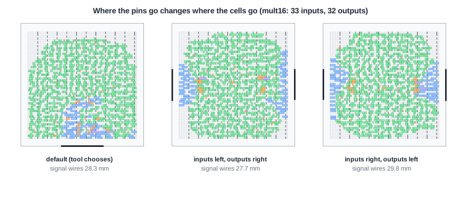
Three runs of the multiplier, identical except for the pin constraints:
| Pins | I/O HPWL estimate | Signal wire after routing | Worst slack at 10 ns |
|---|---|---|---|
| default (tool chooses) | 6,674 um | 28.3 mm | +0.58 ns |
| inputs left, outputs right | 6,421 um | 27.7 mm | +0.54 ns |
| inputs right, outputs left | 6,421 um | 29.8 mm | +0.51 ns |
In the default run the pin placer put the pins together on the bottom edge, and the input and output registers (blue) gathered there. With inputs on one side and outputs on the other, the registers split into two groups at opposite edges and the logic spreads between them. The pin-only estimate is the same for both constrained runs, but after placement and routing the second one needs 2.1 mm (7.6 %) more wire. The estimate looks only at the pins; the real cost depends on how the logic inside lines up with them.
Quick Check
Q: Why do the input and output registers move when the pins move?
Show Answer
Global placement minimizes wire length, and each register is connected directly to a pin. Pulling the register towards its pin shortens that net, so the registers follow the pins, and the logic connected to them follows the registers.
Constraining Pins
OpenROAD constrains pins before place_pins:
set_io_pin_constraint -direction input  -region left:*
set_io_pin_constraint -direction output -region right:*
place_pins -hor_layers met3 -ver_layers met2
-region left:* means anywhere on the left edge; a range such as bottom:20-80 limits pins to part of an edge. Constraints can also select pins by name (-pin_names {a* b*}), keep a bus together and in order (-group -order), or fix a single pin exactly with place_pin. In the lab, these lines go into the OpenROAD script, which PRO users can edit.
Pin Placement in a Real Chip
- Follow the chip floorplan: a block's pins face the blocks they connect to. The top-level floorplan decides which edge each interface uses.
- Keep buses together and in order: bit 0 next to bit 1, so the wires do not cross each other between blocks.
- Mind the clock: the clock pin is usually placed so the clock tree can start near the middle of the block.
- Leave room: many pins on one short edge cause congestion in the margin; spread them or use more layers.
Quick Check
Q: A block has 300 pins on its top edge, which is 100 um long. Pins on met2 need a 0.46 um track each and a free track between neighbours. Do they fit?
Show Answer
No. With one free track between pins, each pin needs 0.92 um, so 100 um holds about 108 pins. The pins must be spread over more edges, put on more layers, or the edge must be longer.
Running It in ChipVerify Lab
Run Place and Route on the multiplier and find the pins in the layout viewer: which edge did the pin placer choose? With PRO, add the two set_io_pin_constraint lines before place_pins in the OpenROAD script and compare the placement.
Common Mistakes
Mistake #1: Leaving pins unconstrained in a block that goes into a chip
The pin placer optimizes the block alone. Its choice may put a pin on the side facing away from the block it connects to, adding long wires at the top level.
Mistake #2: Judging pin placement by the pin HPWL alone
Two placements with the same pin estimate can end with very different wire lengths. Compare after placement, or better after routing.
Practice Exercise
Challenge: Inputs Top, Outputs Bottom
Predict what happens to the multiplier if the inputs a and b go on the top edge and the outputs p on the bottom edge. Where will the registers end up? With PRO, write the constraints and run it.
Hint
Use -region top:* and -region bottom:*. The clock is an input too.
Solution
The constraints are set_io_pin_constraint -direction input -region top:* and set_io_pin_constraint -direction output -region bottom:*. The input registers ra and rb gather along the top edge and the output registers p along the bottom, with the multiplier logic in between, the same pattern as the left/right run turned by 90 degrees. The pin estimate is 6,188 um, the routed design has 27.7 mm of signal wire, practically the same as the left/right run, and the worst slack is +0.48 ns.
Open the ready-made example in the lab, synthesize it and run Place and Route.
Summary
- The lab's flow places pins with
place_pins: met3 on the left and right edges, met2 on the top and bottom. - Pins pull their registers, and with them the logic, towards the edge they sit on.
- For the multiplier, pin constraints changed the routed wire length from 27.7 to 29.8 mm.
set_io_pin_constraintrestricts pins by direction or name to edges or ranges; buses can be grouped and ordered.