
Every block in an SoC typically passes its own UVM regression before it ever reaches the SoC bench. So what's left to verify? Quite a lot, and it's a different kind of problem than block-level testing solves - one where a handful of components, a lot of indirection through software, and a much harder debug process all change how the work gets done. This article walks through what SoC verification actually targets, why its test cases are harder to construct than block-level ones, and where it fits into a real project timeline.
11 min read | Beginner Level
What You'll Learn
- The building blocks that make up a typical SoC and how they relate to each other
- The major categories of bugs that only exist once blocks are integrated
- Why system-level test cases are harder to construct and debug than block-level ones
- When SoC verification starts in a project, and how block-level maturity gates deeper integration testing
Why This Is Worth Getting Right
A block-level bug is usually caught cheaply, early, in a regression that reruns in minutes. A bug that only shows up once the whole chip is assembled is a different story - it tends to surface late, and the cost of fixing it climbs fast the later it's found:
| Stage Bug Is Found | Relative Cost to Fix | Typical Impact |
|---|---|---|
| RTL simulation | 1x | Fix the code, re-run the test |
| Post-synthesis / gate-level | 10x | Design iteration required |
| Silicon (post-fabrication) | 100x | Chip re-spin, $500K-$5M+ |
| Field (in customer hands) | 1000x | Product recall, reputation damage |
Everything in this article is a bug category that block-level verification structurally cannot catch, because it doesn't exist until the blocks are wired together. That's exactly why SoC verification needs its own set of techniques, and its own dedicated bench.
The Building Blocks of a Typical SoC
Before touring what gets verified, it helps to name what's actually on the chip. A typical SoC combines:
- One or more processor cores, sometimes as a cluster sharing a common cache
- A memory subsystem - on-chip SRAM and an external DRAM controller
- An interconnect (or network-on-chip) that every other block routes through to reach memory or each other
- One or more DMA engines that move data between memory and peripherals without core involvement
- Peripherals - UART, SPI, I2C, timers, display or camera interfaces, and similar blocks
- An interrupt controller that aggregates and prioritizes interrupts from every peripheral
- Clock and reset logic, usually spanning several independent domains
- Power management logic controlling voltage domains and low-power states
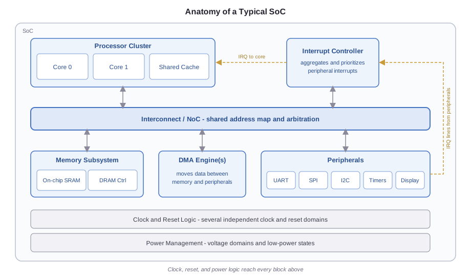
This series won't teach how to verify any single peripheral's protocol in depth - that's block-level verification territory, and each of these blocks already has its own UVM environment before it ever reaches the SoC bench. What matters here is how these pieces interact once they're all connected.
A Quick Tour of What SoC Verification Targets
Think of this as a preview. Each of these areas gets its own chapter later in the series - here, the goal is just to see the shape of the whole problem.
Cross-Block Data Movement
A DMA controller and a peripheral can each pass their IP-level regressions independently and still fail together. A classic SoC-level bug: a DMA engine writes into a peripheral's FIFO while an interrupt handler on the core is simultaneously draining it, and a race condition corrupts the data - a scenario that simply doesn't exist until both blocks are connected to the same system.
Interconnect, Address Maps, and Connectivity
Every block sits behind a shared interconnect and a shared address map. SoC verification checks that address decode is correct (no overlaps, no illegal aliasing), that arbitration between competing masters behaves fairly, and that every pin, mux select, and interrupt line is actually wired to where the spec says it should be. That last check - connectivity - is often done with formal tools rather than simulation, since simulating every wire in a large SoC is impractical.
Interrupts and Shared Resources
An interrupt controller, several peripherals, and one or more cores all contend for the same resources. SoC verification checks interrupt routing, priority, and masking under realistic conditions - for example, confirming an interrupt raised during a critical section is correctly held pending rather than lost.
Multi-Core Behavior and Cache Coherency
Once there's more than one core, shared memory introduces ordering and coherency concerns that simply don't exist in a single-core block-level environment. A value written by one core has to become visible to another core in a way that respects the chip's coherency protocol - and verifying that often involves comparing the RTL's execution against an instruction set simulator, instruction by instruction.
Clock and Reset Domains
An SoC typically has several clock domains and several reset domains converging in one place. Verification here focuses on what happens at those boundaries - not just whether a synchronizer is structurally present, but whether the system behaves correctly when domains power up, reset, or switch frequency at different times relative to each other.
Power-Aware Behavior
Modern SoCs power down unused blocks to save energy, which means verification has to check what happens when a block loses power mid-transaction, whether isolation cells correctly clamp its outputs, and whether state is correctly retained and restored across a power cycle.
Software-Driven Verification
At the IP level, stimulus comes entirely from SystemVerilog sequences. At the SoC level, the cores are part of the design, so the most realistic stimulus is often a short C program running on the core itself - configuring a DMA transfer, waiting on an interrupt, checking a status register - the same way real firmware will.
System-Level Stimulus and Coverage
Constrained-random stimulus that works well at block level doesn't scale the same way once the state space includes every block on the chip. SoC verification uses randomization more selectively, and measures coverage in terms of cross-block scenarios rather than protocol-level detail that's already covered at the IP level.
Emulation and Prototyping
Some scenarios - booting an operating system, running a large software stack, checking system-level performance - are too slow to exercise in RTL simulation. Emulators and FPGA prototypes run orders of magnitude faster, making them the practical choice once the bench needs to run real software at scale.
Why System-Level Test Cases Are Hard to Construct
At the block level, hitting a corner case is usually a matter of writing a few lines of a sequence. You drive the interface directly, so you can force almost any condition on the very first cycle of a test.
At the SoC level, that direct control mostly disappears. To exercise a particular condition in one block, a test usually has to set up several other blocks correctly first, and then let real hardware and software carry the scenario through to the block being targeted. Consider a FIFO-almost-full condition on a peripheral fed by DMA: reaching it requires configuring DMA descriptors correctly, timing the peripheral's own consumption rate, and possibly synchronizing with an interrupt handler - three or four moving parts that all have to line up, none of which the test controls directly.
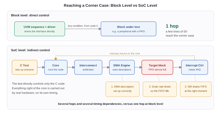
That indirection has a real consequence: a corner case that takes five lines of SystemVerilog to force at block level might take an elaborate, carefully sequenced C test and SV scenario together to reach at SoC level, and some corner cases simply aren't practical to reach this way at all. That's a feature, not a gap - exhaustive corner-case coverage stays the responsibility of block-level verification. SoC verification instead focuses on realistic combinations of blocks working together, the kind of scenario a single block's testbench has no way to construct.
The Debug Cost of System-Level Bugs
A block-level test failure is usually close to its cause. The testbench is small, the test is short, and the waveform covers a handful of interfaces - tracing a failure back to its root cause is often quick.
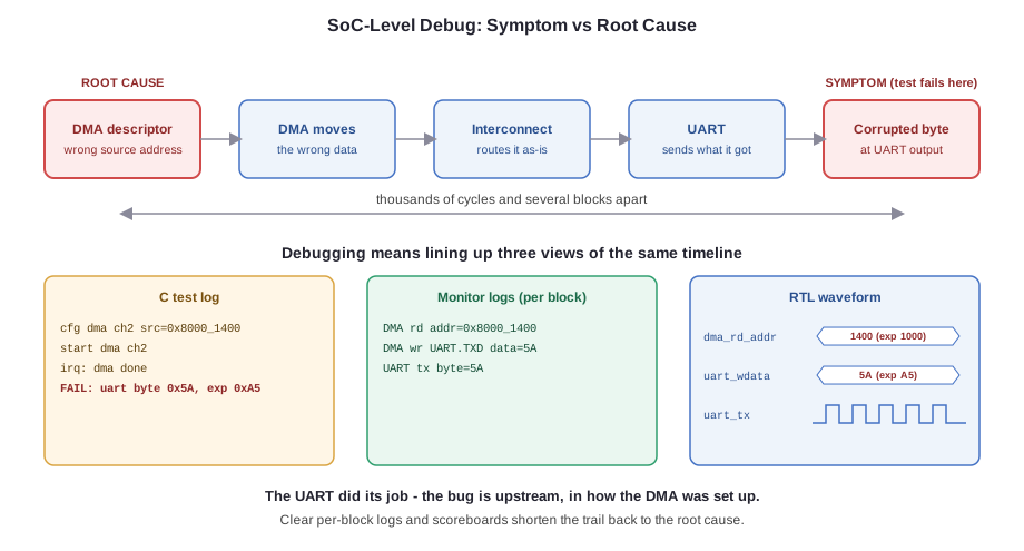
An SoC-level failure is a different experience. The symptom might surface thousands of cycles after the actual root cause, deep into a C test's execution, after passing through several blocks and possibly through more than one layer of software. Debugging it usually means correlating three views of the same timeline at once: the C test's own log output, transaction logs from several passive monitors scattered across the chip, and the RTL waveform itself.
The root cause is often several hops removed from where the symptom appears. A corrupted byte observed in a UART's output register might actually trace back to a DMA descriptor that was misconfigured several transactions earlier - the UART simply faithfully transmitted bad data it was given. This is why SoC-level regressions tend to run longer and debug cycles take longer to close, and why disciplined logging and scoreboarding - covered later in this series - matter more here than almost anywhere else in verification.
Where SoC Verification Fits in the Project Timeline
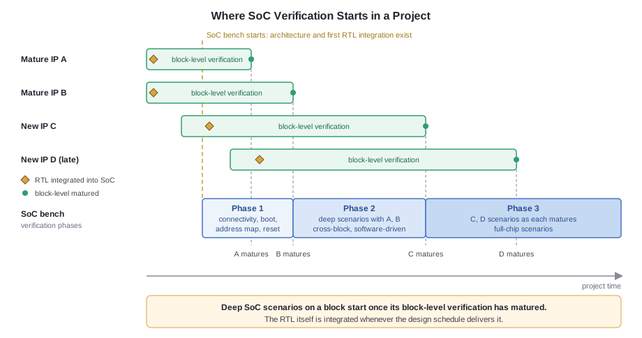
Design and verification run on separate clocks. Each block's RTL is delivered and integrated into the SoC database on the design team's schedule, whether or not that block's own verification is finished. A new IP often arrives as an early, incomplete drop, and updated drops keep landing as bugs are fixed. Behavioral or bus-functional stub models only stand in for IPs that haven't been delivered at all.
SoC verification starts once the architecture and a first pass of integration exist, and its first tests don't depend on any block's internals. Connectivity, address map, reset, clocking, and basic boot checks can run on whatever RTL is in the database, immature or not.
True integration testing is different. A test that pushes DMA data through a peripheral or exercises its interrupt behavior is only meaningful once that block's own verification has matured: its functionality is largely verified and the major bugs are flushed. Before that point, an SoC-level failure is more likely a block bug that block-level verification would find anyway, so the same bug gets debugged twice, through a much longer path.
Blocks reach that point at different times. A mature IP reused from a previous chip is ready almost immediately, while a newly designed IP may not be until late in the project. Later in this series, we look at how a verification plan tracks each block's maturity alongside the SoC-level test list itself.
Where This Shows Up in Industry
Smartphone application processors rely on this kind of verification to get cache coherency and power management right across multiple cores. Automotive SoCs use it to meet safety-critical requirements. AI accelerators depend on it to confirm high-throughput data paths behave correctly under realistic, concurrent traffic - not just in isolation.
Common Misconceptions
"SoC verification just means running the same block-level tests on a bigger testbench."
Block-level tests are rarely reused as-is. What gets reused is the verification IP itself - drivers, monitors, checkers. The scenarios are new, and they specifically target the cross-block interactions described above, which don't exist at the IP level.
"If every block passes its own regression, the SoC is basically guaranteed to work."
Every category in this article - interconnect, interrupts, coherency, power, clocking - is a class of bug that only exists once blocks are connected. A 100% pass rate at the block level says nothing about any of them.
"SoC verification can only start once every block in the design is fully verified."
SoC verification starts much earlier, with integration checks like connectivity, address map, and boot running on whatever RTL has been delivered. What waits is narrower: deep end-to-end scenarios involving a particular block become meaningful once that block's own verification has matured, and blocks mature at different times.
Quick Check
Q: A UART block passes 100% of its IP-level UVM regression. Does that mean UART-related bugs are impossible at the SoC level?
Show Answer
No. IP-level verification only proves the UART block is correct in isolation. Bugs can still appear at the SoC level from how the UART interacts with other blocks - for example, incorrect interrupt routing, DMA misconfiguration when feeding the UART, or an address decode error that routes accesses to the wrong register.
Practice Exercise
Challenge: Categorize the Bug
An SoC has two peripherals mapped to adjacent, non-overlapping address ranges. Both pass their IP-level tests. At the SoC level, a write to a register in Peripheral A causes an unexpected bit change in Peripheral B. Which of the target areas from this article is responsible for catching this, and why couldn't it have been caught at the IP level?
Hint
Think about which category of verification involves the shared address map.
Solution
This falls under interconnect and address map verification, specifically address decode. Each IP-level testbench only exercises its own block in isolation and has no concept of a shared address map or a neighboring peripheral. The bug - most likely an address decode overlap or aliasing issue - only exists once both blocks are connected to the same system address map, which happens for the first time at the SoC level.
Summary
In this tutorial, you learned:
- A typical SoC combines cores, a memory subsystem, an interconnect, DMA engines, peripherals, an interrupt controller, and clock/reset/power logic - and SoC verification is about how these pieces behave together
- SoC verification exists because bugs in cross-block data movement, interconnect behavior, interrupts, coherency, clocking, and power only show up once blocks are integrated
- System-level test cases are harder to construct than block-level ones, since reaching a specific condition usually requires several blocks and software to line up rather than direct control over one interface
- Debugging an SoC-level failure typically means correlating C test logs, multiple monitor transaction logs, and RTL waveforms, since the root cause is often several hops from where the symptom appears
- RTL is integrated on the design schedule and SoC verification starts early with integration checks, but deep end-to-end scenarios on a block only become meaningful once that block's own verification has matured
The rest of this series explores each of these areas in depth.
