
In OpenROAD, clock tree synthesis is one command, clock_tree_synthesis, run by the TritonCTS tool after placement. It finds the clock nets, picks clock buffers from the library, builds a balanced tree, inserts dummy loads to even out the leaves, and legalizes the new cells. This article walks through what the command does in the lab's flow for the 16x16 multiplier, how to read its log and reports, and how to check the resulting tree.
8 min read | Intermediate
What You'll Learn
- Place CTS in the lab's OpenROAD flow
- Read the TritonCTS log: buffers, sinks, levels and fanout
- Explain why CTS adds dummy loads
- Check skew and latency with propagated clocks
CTS in the Lab's Flow
The lab's OpenROAD script runs CTS right after the first detailed placement:
if {$has_clock} {
    clock_tree_synthesis -apply_ndr none
    set_propagated_clock [all_clocks]
    estimate_parasitics -placement
    repair_timing -setup
    repair_timing -hold
    detailed_placement
    report_cts -out_file cts_report.txt
}
Four things are worth knowing about this block:
- It runs only when the design has a clock port. The flow takes the input that drives the most flip-flop and clock gate CLK pins, and falls back to common names such as
clk,clockorclk_i; PRO users can name the port in the panel. - The clock itself,
create_clockwith the period from the panel, was created at the start of the script, so placement already had the constraint; see Timing- and Congestion-Driven Placement. - After CTS the clock is propagated, setup and then hold are repaired, and a second detailed placement legalizes the clock buffers and any cells that repair added. Post-CTS Optimization covers that step.
-apply_ndr noneturns off a default of this CTS version that gives clock nets double width and spacing. With 32 gated clocks in one design, those wider wires made global routing fail, so the lab applies such a rule only through its PRO Clock NDR option; see Crosstalk, Shielding and Non-Default Rules.
Earlier in the script, set_layer_rc gives every metal layer its resistance and capacitance, and set_wire_rc -clock -layer met3 tells the parasitic estimator to assume clock wires have the values of met3, while signal wires are estimated as met1.
Choosing the Buffers
TritonCTS first picks which clock buffers to use and characterizes them, building tables of delay and slew for wire segments driven by each buffer:
[INFO CTS-0050] Root buffer is sky130_fd_sc_hd__clkbuf_16.
[INFO CTS-0051] Sink buffer is sky130_fd_sc_hd__clkbuf_16.
[INFO CTS-0052] The following clock buffers will be used for CTS:
                    sky130_fd_sc_hd__clkbuf_16
[INFO CTS-0049] Characterization buffer is sky130_fd_sc_hd__clkbuf_16.
The choice depends on the design. For a 64-bit shift register, a smaller block with short clock wires, the same command picked clkbuf_4 and clkbuf_8 instead. Clock buffers (clkbuf) differ from ordinary buffers in having balanced rise and fall delays, which keeps the clock's duty cycle intact as the edge passes through several stages. The buffer list can be set explicitly with -buf_list and -root_buf.
Reading the Result
[INFO CTS-0007] Net "clk" found for clock "clk".
[INFO CTS-0010]  Clock net "clk" has 64 sinks.
[INFO CTS-0008] TritonCTS found 1 clock nets.
[INFO CTS-0018]     Created 9 clock buffers.
[INFO CTS-0012]     Minimum number of buffers in the clock path: 2.
[INFO CTS-0013]     Maximum number of buffers in the clock path: 2.
[INFO CTS-0015]     Created 9 clock nets.
[INFO CTS-0016]     Fanout distribution for the current clock = 5:1, 6:2, 8:2, 9:1, 10:1, 12:1..
[INFO CTS-0017]     Max level of the clock tree: 3.
[INFO CTS-0098] Clock net "clk"
[INFO CTS-0099]  Sinks 71
[INFO CTS-0101]  Average sink wire length 134.70 um
[INFO CTS-0102]  Path depth 2 - 2
[INFO CTS-0207]  Dummy loads inserted 7
- 64 sinks: the CLK pins of the 64 flip-flops.
- 9 clock buffers: one root and eight leaf buffers. Every clock path goes through exactly two of them (minimum and maximum both 2), which is the first sign of a balanced tree.
- Fanout distribution: one leaf buffer drives 5 flip-flops, two drive 6, two drive 8, and one each drives 9, 10 and 12, 64 in total.
- Sinks 71: the 64 flip-flops plus 7 dummy loads.
Dummy Loads
A leaf buffer driving 5 flip-flops is faster than one driving 12, because it sees less capacitance. To even out the delays, TritonCTS attaches extra cells to the lightly loaded leaves. They have their inputs on the clock net and drive nothing, acting purely as capacitance. The CTS report lists them:
Total number of Clock Roots: 1.
Total number of Buffers Inserted: 9.
Total number of Clock Subnets: 9.
Total number of Sinks: 64.
Buffers used:
  sky130_fd_sc_hd__clkbuf_16: 9
Dummys used:
  sky130_fd_sc_hd__bufinv_16: 2
  sky130_fd_sc_hd__clkbuf_8: 1
  sky130_fd_sc_hd__clkinv_2: 1
  sky130_fd_sc_hd__clkinv_4: 2
  sky130_fd_sc_hd__inv_6: 1
Dummy loads cost area and clock power, but they are a cheap way to match latencies without rebuilding the tree.
Quick Check
Q: A leaf buffer drives 5 flip-flops and another drives 12. Without any correction, which group of flip-flops sees the clock edge later, and what does the tool do about it?
Show Answer
The group behind the buffer with 12 loads, because the larger capacitance slows that buffer's output. TritonCTS adds dummy loads to the lightly loaded buffer so both buffers see a similar load and have a similar delay.
The Tree in the Layout
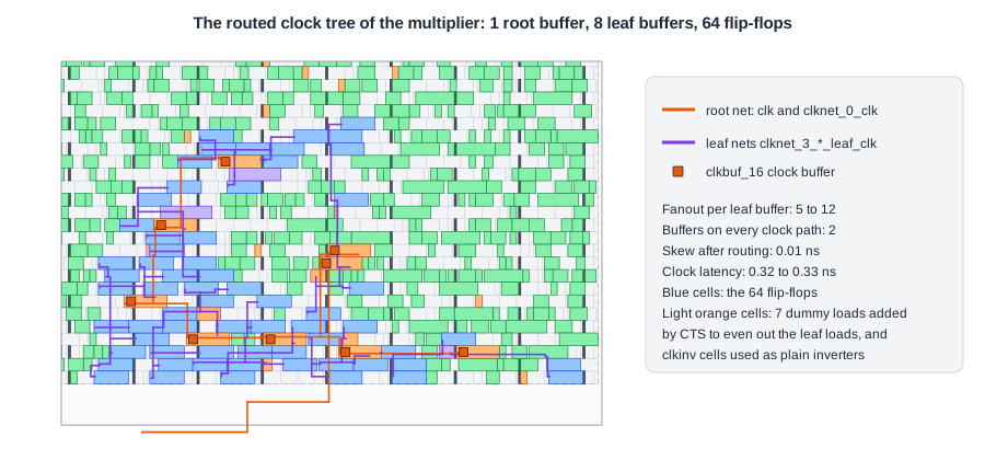
All the flip-flops of the multiplier sit in the lower half of the core, close to the I/O pins on the bottom edge. The clock enters from the bottom, runs to the root buffer, and the root net fans out to the eight leaf buffers, each placed in the middle of its group of flip-flops. CTS places its buffers at ideal positions; the detailed placement after CTS moves them to legal sites, and the routed result is what the picture shows.
Checking Skew and Latency
CTS does not switch the timing engine to the real clock by itself. To see the tree's effect on timing, propagate the clock and update the parasitics, as the lab's script does right after CTS:
set_propagated_clock [all_clocks]
estimate_parasitics -placement
report_clock_skew -setup
report_checks -path_delay min -format full_clock_expanded
Clock clk
   0.32 source latency _2432_/CLK ^
  -0.33 target latency _2414_/CLK ^
   0.00 CRPR
--------------
  -0.01 setup skew
With -format full_clock_expanded, every timing path shows the clock path to both flip-flops, buffer by buffer. From the final report of the routed multiplier:
   0.00    0.00 ^ clk (in)
   0.16    0.16 ^ clkbuf_0_clk/X (sky130_fd_sc_hd__clkbuf_16)
   0.16    0.32 ^ clkbuf_3_4__f_clk/X (sky130_fd_sc_hd__clkbuf_16)
   0.00    0.32 ^ _2432_/CLK (sky130_fd_sc_hd__dfxtp_1)
...
   0.00    0.00 ^ clk (in)
   0.16    0.16 ^ clkbuf_0_clk/X (sky130_fd_sc_hd__clkbuf_16)
   0.16    0.33 ^ clkbuf_3_6__f_clk/X (sky130_fd_sc_hd__clkbuf_16)
   0.00    0.33 ^ _2448_/CLK (sky130_fd_sc_hd__dfxtp_1)
   0.00    0.33   clock reconvergence pessimism
The launch and capture flip-flops hang off different leaf buffers, clkbuf_3_4__f_clk and clkbuf_3_6__f_clk, and the two clock paths differ by only 0.005 ns. The names show the structure: clkbuf_0 is the root, and clkbuf_3_* are leaves at level 3 of the H-tree topology, eight of them.
In the lab's report, the clock section shows the same numbers for the routed design: 0.32 to 0.33 ns of latency and 0.01 ns of setup skew.
Quick Check
Q: Why does the report show a "clock reconvergence pessimism" line, and why is it zero here?
Show Answer
When the launch and capture clock paths share buffers, an analysis with different delays for early and late paths would count the shared part twice. CRPR removes that double count. Here the analysis uses one set of delays for both, so the correction is zero. It becomes non-zero with on-chip variation derates, as On-Chip Variation, Derates and Sign-Off Corners shows on the routed multiplier.
Running It in ChipVerify Lab
Run Place and Route on the multiplier, find the CTS section of the log and check the numbers above: sinks, buffers, buffers per path, fanout distribution and dummy loads. Then open the layout and find the clock buffers, whose names start with clkbuf_. The CTS section of the report has the summary of report_cts: buffers, sinks and the dummy loads.
Common Mistakes
Mistake #1: Assuming the flow always finds the clock
The lab's script takes the input that drives the most flip-flop clock pins as the clock. If the clock reaches the flip-flops only through logic, and the port has an unusual name, no clock is found: there is no clock tree and no timing check at all. Check the log for the clock net CTS found, and name the port explicitly when in doubt.
Mistake #2: Reading timing right after CTS without propagating the clock
Until set_propagated_clock, the timing engine still uses an ideal clock with zero latency, and the reports do not show the tree.
Mistake #3: Removing dummy loads as "unused cells"
They have no output connection on purpose. They are part of the clock tree's balancing, and removing them changes the latencies.
Practice Exercise
Challenge: Average Load per Leaf
The multiplier's tree has 8 leaf buffers for 64 flip-flops and an average sink wire length of 135 um. How many flip-flops does each leaf buffer drive on average? Why does the root buffer need to drive only eight loads, even though it is the same cell type?
Hint
Look at what the root buffer's net connects to.
Solution
64 / 8 = 8 flip-flops per leaf buffer on average, 5 to 12 in practice. The root drives only the eight leaf buffers, but over longer wires that span the whole flip-flop area. Its load is mostly wire capacitance, the leaves' load is mostly flip-flop clock pins.
Open the ready-made example in the lab, synthesize it and run Place and Route.
Summary
- The lab runs
clock_tree_synthesisafter placement, for the clock port it detects, then propagates the clock and repairs setup and hold. - TritonCTS picks and characterizes clock buffers, builds the tree and adds dummy loads to balance light leaves.
- For the multiplier: 9 buffers, 2 per path, fanouts 5 to 12, 7 dummy loads.
- Propagate the clock to see the tree in timing reports; the multiplier's tree has 0.32 to 0.33 ns latency and 0.01 ns skew.
-format full_clock_expandedshows the clock path buffer by buffer.