
In OpenROAD, the power grid is built by the PDN generator, pdngen. A short script tells it which nets are power and ground, which layers to use, and how wide and how far apart the straps should be; pdngen then draws the rails, straps and vias in one step. This article walks through a complete power grid script for sky130, compares the rails-only grid of the lab's default flow with a full grid, and shows how to check that the grid is connected.
9 min read | Intermediate
What You'll Learn
- Write the OpenROAD commands that build a power grid
- Connect the power pins of every cell to the supply nets
- Explain why a rails-only grid fails power analysis
- Fix the two most common pdngen errors on small cores
Step 1: Connect the Power Pins
A netlist from synthesis has no power nets: the cells' VPWR and VGND pins are not connected to anything. The first step tells OpenROAD which pins belong to which supply:
add_global_connection -net VDD -inst_pattern .* -pin_pattern VPWR -power
add_global_connection -net VSS -inst_pattern .* -pin_pattern VGND -ground
global_connect
The patterns are regular expressions: every instance (.*), the pin named VPWR, goes to VDD. -power and -ground mark the nets as supply nets. The lab's script also adds the same lines for VPB and VNB, the well and substrate pins. In the sky130 hd LEF the cells have no such pins, so those two lines connect nothing; the wells are tied by the tap cells, see Tap Cells, Endcaps, Latch-Up and Decaps.
Step 2: Define the Grid
set_voltage_domain -name CORE -power VDD -ground VSS
define_pdn_grid -name grid -voltage_domains CORE
A voltage domain names the power and ground nets of a region; a design with one supply has one domain, CORE, covering the whole core. define_pdn_grid creates an empty grid for that domain. Everything added next goes into it.
Step 3: Rails, Straps and Vias
add_pdn_stripe -grid grid -layer met1 -width 0.48 -pitch 5.44 -offset 0 -followpins
add_pdn_stripe -grid grid -layer met4 -width 1.60 -pitch 27.14 -offset 6.79
add_pdn_stripe -grid grid -layer met5 -width 1.60 -pitch 27.20 -offset 6.80
add_pdn_connect -grid grid -layers {met1 met4}
add_pdn_connect -grid grid -layers {met4 met5}
pdngen
-followpinsmakes the met1 stripes rails along the rows. The pitch 5.44 um is two row heights (2 x 2.72): the rails of one net repeat every second row.- The met4 and met5 lines add straps. For each net, the pitch is the distance between its straps; VDD and VSS straps are placed alternately, half a pitch apart.
add_pdn_connectadds vias wherever the two layers cross on the same net. From met1 to met4, pdngen builds the whole stack through met2 and met3.pdngenbuilds the grid in the database.
The pitches and widths are those of the OpenROAD flow scripts for sky130hd. The log reports only [INFO PDN-0001] Inserting grid: grid; the result shows up in the layout and in the DEF, as special nets with + USE POWER and + USE GROUND.
Quick Check
Q: The script has add_pdn_connect for met1-met4 and met4-met5. What happens if the met4-met5 line is left out?
Show Answer
pdngen draws the met5 straps but no vias between met4 and met5. The met5 straps float: they are on the VDD and VSS nets by name, but carry no current to the cells. Power analysis reports them as unconnected shapes.
Rails Only: Why It Fails
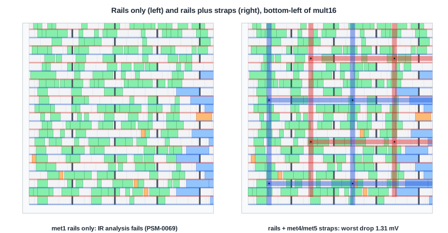
The lab's default script, at the time of writing, has only the first add_pdn_stripe line, the met1 rails. The run completes and the layout looks fine, but the power analysis at the end fails:
[WARNING PSM-0038] Unconnected shape on net VDD at (10.580um, 78.795um) - (15.640um, 78.965um), layer: li1.
...
[ERROR PSM-0069] Check connectivity failed on VDD.
The multiplier run printed 1,001 PSM-0038 warnings before the error. The reason is simple: with rails only, each rail is a separate piece of metal. Rail 1 touches the cells of rows 1 and 2, rail 3 those of rows 3 and 4, and nothing connects rail 1 to rail 3. There is no single VDD network from a supply to the cells, so there is nothing to analyze. In a real chip the design would not work at all, because the rails have no connection to the package.
With the straps and vias added, the same design reports:
[INFO PSM-0040] All shapes on net VDD are connected.
Preparing the Power Analysis
The IR drop analysis, analyze_power_grid, needs two more inputs that sky130's tech LEF does not supply: the resistance of the vias and the supply voltage.
set_layer_rc -via mcon -resistance 9.249146E-3
set_layer_rc -via via  -resistance 4.5E-3
set_layer_rc -via via2 -resistance 3.368786E-3
set_layer_rc -via via3 -resistance 0.376635E-3
set_layer_rc -via via4 -resistance 0.00580E-3
set_pdnsim_net_voltage -net VDD -voltage 1.8
set_pdnsim_net_voltage -net VSS -voltage 0.0
analyze_power_grid -net VDD
The via resistances are again the values from the OpenROAD flow scripts for sky130hd. Without them the analysis stops with PSM-0021 (no via resistance); without the voltage it cannot tell what the cells should see. IR Drop: Static and Dynamic reads the results.
Errors on Small Cores
The fixed pitch of 27 um does not fit every core. On a 26 um core, pdngen stops:
[ERROR PDN-0185] Insufficient width (26.22 um) to add straps on layer met4 in grid "grid" with total strap width 15.2 um and offset 13.6 um.
The pitch can be computed from the core size instead, for example half the core width when that is smaller than 27.14 um. But a computed number must land on the manufacturing grid of 5 nm:
[ERROR PDN-0191] Offset of 3.2780 um does not fit the manufacturing grid of 0.0050 um.
The fix is to round every computed pitch and offset, here to 0.01 um:
set core [[ord::get_db_block] getCoreArea]
proc on_grid {v} { format %.2f [expr {round($v * 100.0) / 100.0}] }
set p4 [on_grid [expr {min(27.14, [ord::dbu_to_microns [$core dx]] / 2.0)}]]
add_pdn_stripe -grid grid -layer met4 -width 1.60 -pitch $p4 -offset [on_grid [expr {$p4 / 4.0}]]
Quick Check
Q: Why is rounding to 0.01 um safe when the manufacturing grid is 0.005 um?
Show Answer
Every multiple of 0.01 is also a multiple of 0.005, so a value rounded to two decimals always lies on the manufacturing grid.
Adding a Ring
A core ring is one more command, before pdngen:
add_pdn_ring -grid grid -layers {met4 met5} -widths 2.0 -spacings 1.6 -core_offsets 2.0
The first layer carries the vertical sides of the ring and the second the horizontal ones. For the straps to reach the ring, add -extend_to_core_ring to the met4 and met5 add_pdn_stripe lines. Without it, the ring is drawn but connected to nothing, and the power analysis reports it as an unconnected shape and fails with PSM-0069.
Running It in ChipVerify Lab
Run Place and Route on the multiplier and search the log for PDN and PSM messages. If the run reports PSM-0069, the grid has rails only. With PRO, paste a custom OpenROAD script based on the lab's own script with the strap, connect, via resistance and voltage lines of this article added, and run again: the PSM messages should change to "All shapes on net VDD are connected", followed by the IR drop numbers.
Common Mistakes
Mistake #1: Straps without add_pdn_connect
Straps drawn without vias carry no current. Every pair of layers that should be joined needs its own add_pdn_connect.
Mistake #2: Trusting a run that completes
A design with a broken grid places and routes without complaint. Only the connectivity check of the power analysis, or LVS, shows that the supplies never reach the cells.
Mistake #3: Computing coordinates without rounding
Any pitch or offset computed from the core size must be rounded to the manufacturing grid, or pdngen stops with PDN-0191.
Practice Exercise
Challenge: Count the Rails
The multiplier's core has 56 rows. How many met1 rails does pdngen draw, how many are VDD and how many VSS? Without straps, into how many separate pieces does the VDD network fall apart?
Hint
Rows share the rail between them. Count the row boundaries, including the bottom and top edges.
Solution
56 rows have 57 boundaries, so 57 rails, alternating VSS and VDD: 29 VSS and 28 VDD in the multiplier. Without straps, every VDD rail is its own piece, so the VDD network is 28 unconnected pieces, plus any cell that touches none of them. The straps join them into one network.
Open the ready-made example in the lab, synthesize it and run Place and Route.
Summary
add_global_connectionandglobal_connecttie the cells' VPWR and VGND pins to VDD and VSS.define_pdn_grid,add_pdn_stripe,add_pdn_connectandpdngenbuild the rails, straps and vias.- A rails-only grid is a set of disconnected rails: power analysis fails with PSM-0069.
- Power analysis also needs via resistances (
set_layer_rc -via) and the supply voltage (set_pdnsim_net_voltage). - Pitches computed for small cores avoid PDN-0185; rounding avoids PDN-0191.
