
Two wires running side by side form a capacitor. When one of them switches, part of its charge flows through that capacitance into its neighbour, and the neighbour's voltage moves. This is crosstalk. On a chip where neighbouring wires sit a fraction of a micrometre apart, it is a large part of every net's load. This article measures how large on the routed 16x16 multiplier, explains the two ways crosstalk causes failures, and tests the standard fix for clock nets, a non-default rule with double width and spacing.
7 min read | Intermediate
What You'll Learn
- Explain coupling capacitance and the two effects of crosstalk
- Read coupling capacitance from an extracted SPEF file
- Describe shielding, spacing and non-default rules as fixes
- Create and assign a non-default rule for clock nets in OpenROAD
Coupling Capacitance
A wire has capacitance to the layers above and below it, the ground capacitance Cg, and capacitance to the wires beside it on the same layer, the coupling capacitance Cc. Coupling capacitance grows with the length over which two wires run in parallel and falls with the spacing between them.
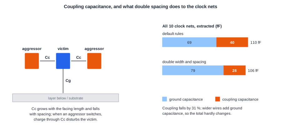
The wire being disturbed is called the victim, the switching neighbour the aggressor. Every net is a victim of some neighbours and an aggressor to others.
How Large Is It?
The lab's flow extracts every routed design with OpenROAD's extractor, OpenRCX, using the sky130 extraction rules that ship with OpenROAD-flow-scripts:
define_process_corner -ext_model_index 0 X
extract_parasitics -ext_model_file /OpenROAD-flow-scripts/flow/platforms/sky130hd/rcx_patterns.rules
write_spef layout.spef
The SPEF file lists every net's capacitance, with ground capacitances (one node) and coupling capacitances (two nodes, one on each net) separately. Summed over the multiplier:
| Nets | Total capacitance | Coupling part | Coupling share |
|---|---|---|---|
| 1,299 signal nets | 4,385 fF | 1,724 fF | 39 % |
| 10 clock nets | 104 fF | 41 fF | 40 % |
About two fifths of the wire load comes from neighbours. For single nets it can be much more: the output net p[9] has 11.5 fF, of which 7.5 fF is coupling, because it runs a long way beside other nets.
Two Effects of Crosstalk
- Noise (glitches). If the victim is quiet and an aggressor switches, the victim gets a short bump. If the bump is large enough and reaches a flip-flop or a latch at the wrong moment, it is captured as a wrong value. Clock and reset nets are most sensitive: a glitch on a clock is an extra clock edge.
- Delay change (delta delay). If victim and aggressor switch at the same time in opposite directions, the coupling capacitance sees twice the voltage swing and the victim slows down; in the same direction, it speeds up. Slower paths can break setup, faster paths can break hold.
Signal integrity tools compute both effects from the coupling capacitances and the switching windows of each net. OpenROAD's timing engine does not model crosstalk delay, so in an open-source flow the coupling capacitance counts as plain load, and the margin for delta delay has to come from design rules and timing margin.
Quick Check
Q: A victim net with 10 fF of coupling to one aggressor switches up while the aggressor switches down. Why does the victim's driver see more than 10 fF of effective load from that capacitor?
Show Answer
The voltage across a coupling capacitor is the difference between the two wires. When both switch in opposite directions, that difference changes by twice the supply voltage, so the driver must move twice the charge, as if the capacitor were up to 20 fF to a fixed ground. When both switch in the same direction, the difference hardly changes and the capacitor almost disappears.
Fixes in the Layout
- Spacing. Coupling falls quickly with distance, so routing a net with double spacing cuts most of it.
- Shielding. Route a grounded or power wire on each side of the victim. The coupling to switching neighbours is replaced by coupling to a quiet supply, which turns into ground capacitance.
- Wider wires. Lower resistance and more drive along the wire, so the victim recovers faster from a bump; the cost is more ground capacitance.
- Layer and order changes. Moving a long net to another layer, or reordering parallel buses, breaks long parallel runs.
- Driver strength. A stronger driver on the victim holds it closer to its value; a weaker or slower aggressor injects less noise.
Spacing, width and shielding are expressed as a non-default rule (NDR): a routing rule for selected nets that replaces the technology's default width and spacing. NDRs are used mainly on clock nets, because clocks switch every cycle, run long distances, and a glitch or delay change on them affects every flop they reach.
A Clock NDR in OpenROAD
OpenROAD's CTS already adds a rule called CTS_NDR_0 with double spacing, at default width, to the top of the tree; in the multiplier it covered the clock input net and the root net, 2 of the 10 clock nets. To put every clock net on double width and spacing, create a rule and assign it before global routing:
create_ndr -name clk2x -spacing {*2} -width {*2}
assign_ndr -ndr clk2x -all_clocks
global_route
*2 means twice the default on every routing layer. Values can also be given per layer as name and value pairs, such as {met1 0.28 met2 0.28}. After the run, the DEF lists both rules in its NONDEFAULTRULES section and marks all 10 clock nets with clk2x.
Extracted with and without the rule:
| Multiplier, 10 ns clock | Default rules | clk2x on all clock nets |
|---|---|---|
| Clock coupling capacitance | 40.1 fF | 27.8 fF |
| Clock ground capacitance | 69.5 fF | 78.7 fF |
| Clock total capacitance | 109.6 fF | 106.4 fF |
| Clock wire length | 741 um | 777 um |
| Detailed routing passes (first-pass violations) | 4 (427) | 5 (497) |
| Worst setup slack, extracted | +0.13 ns | +0.15 ns |
- Coupling on the clock dropped by 31 %, and it no longer depends as much on what the neighbouring signals do.
- The wider wires added ground capacitance, so the total load stayed about the same. The benefit is less noise and less delay variation, not a lighter clock.
- The rule takes tracks from other nets, which made detailed routing slightly harder and the clock wires 5 % longer. On a design with hundreds of clock nets, this is a real congestion cost.
A related control is the clock's layer range. Adding set_routing_layers -clock met3-met4 before global routing moved part of the multiplier's clock wiring from met1 and met2 to met3 and met4, where the wires are wider and the neighbours fewer.
Quick Check
Q: The NDR lowered the clock's coupling capacitance by 12 fF but the total by only 3 fF. Was it worth it?
Show Answer
Yes, for a clock. Ground capacitance is a fixed load that CTS balances like any other, so it costs some power but does not cause noise or unpredictable delay. Coupling capacitance changes with the switching of the neighbours, which shows up as clock glitches and as clock delay variation, so trading coupling for ground capacitance makes the clock tree more predictable.
Running It in ChipVerify Lab
Run Place and Route on the multiplier and note the clock nets in the CTS report; the SPEF file in the report holds the extracted coupling capacitances. With PRO, the Clock NDR option adds create_ndr -name clk2x -spacing {*2} -width {*2} and assign_ndr for all clocks before global routing, and the routing layer options keep signal or clock nets on chosen layers. On the multiplier, the NDR run's DEF gained a NONDEFAULTRULES section with the doubled widths (0.28 um on met1 and met2, 0.6 um on met3 and met4), the routed clock wire grew from 680 to 703 um, and the worst slack stayed within 0.01 ns.
Common Mistakes
Mistake #1: Treating coupling capacitance as ordinary load
It is load, but load that depends on the neighbours' switching. A timing report that counts it as ground capacitance misses both glitches and delta delay.
Mistake #2: Putting an NDR on too many nets
Each NDR net uses two to three tracks. Applied to buses or many signals, NDRs turn a routable design into a congested one. Keep them for clocks and a few sensitive nets.
Mistake #3: Expecting an NDR to reduce clock power
Double width adds as much ground capacitance as double spacing removes coupling. The gain is noise immunity and predictable delay.
Practice Exercise
Challenge: A Victim Net
The net p[9] has 11.5 fF of total capacitance, 7.5 fF of it coupling. Assume all its aggressors switch in the opposite direction at the same time as p[9]. What effective capacitance does its driver see? And if they all switch in the same direction?
Hint
Opposite switching doubles the effect of the coupling part; same-direction switching removes it.
Solution
Ground part: 11.5 - 7.5 = 4.0 fF. Opposite switching: 4.0 + 2 x 7.5 = 19.0 fF, 65 % more than the nominal load. Same direction: about 4.0 fF. The driver's delay can therefore vary by a large factor depending on its neighbours, which is why signal integrity analysis uses switching windows instead of a single capacitance.
Open the ready-made example in the lab, synthesize it and run Place and Route.
Summary
- Coupling capacitance between neighbouring wires was 39 % of the multiplier's signal wire capacitance after extraction.
- Crosstalk causes glitches on quiet victims and delay changes on switching ones.
- Fixes are spacing, shielding, width, layer changes and driver strength; spacing and width are expressed as non-default rules.
- A double width and spacing NDR on all clock nets cut their coupling by 31 % at the cost of longer clock wires and harder detailed routing.
