
A signal does not reach the end of a wire at the moment it leaves the driver. The wire has resistance and capacitance, so it charges like a small RC circuit, and the load pin sees the change a little later. This is the net delay, and the standard way to estimate it is the Elmore delay. This article shows the formula, works through an example with the numbers of a real net, and explains where the estimate is accurate and where it is not.
Think of filling a row of buckets through narrow pipes. The bucket at the far end fills last, because the water has to pass through every pipe on the way and every bucket in front of it also takes some. The Elmore delay is a simple rule that counts exactly this.
8 min read | Intermediate
What You'll Learn
- Explain the difference between cell delay and net delay
- Calculate the Elmore delay of a wire from its resistors and capacitors
- Apply the rule to a tree with branches
- Describe why the wire also degrades the slew and why Elmore is only an estimate
Cell Delay and Net Delay
The delay of a path has two kinds of parts. A cell delay is the time from an input pin of a cell to its output pin, and the library gives it as a table lookup. A net delay is the time from the output pin of the driver to the input pin of a load, and it depends only on the wire.
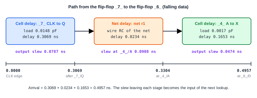
In the diagram, the path of the demo circuit has three parts. The flip-flop _7_ takes 0.3069 ns from the clock to its output. The wire takes another 0.0234 ns to reach the pin _4_/A. The XOR gate takes 0.1653 ns. The arrival time at the end is the sum, 0.4957 ns. With ideal wires the middle part is zero, and that is what the first chapters assumed.
The Elmore Delay
Think of a wire as a chain of resistors with a small capacitor at each node. To raise the voltage at the load, charge must flow through the resistors to fill every capacitor. A capacitor that is far away has to be filled through many resistors, so it takes longer, and the capacitors behind the resistor also matter.
The Elmore delay turns this into a simple rule. For a load pin, go along the path from the driver to that pin. For every resistor on the path, multiply its value by the total capacitance that sits behind it, which means all the capacitance downstream of it, including branches. Then add up the products.
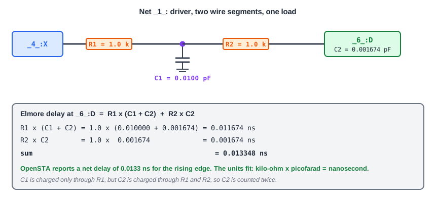
Here is the net _1_ of the demo circuit, with a wire of two segments of 1.0 kilo-ohm each, a wire capacitance of 0.0100 pF in the middle and the load pin of the flip-flop _6_ with 0.001674 pF at the end:
- The first resistor has all the capacitance behind it: 0.0100 + 0.001674 pF.
- The second resistor has only the capacitance of the pin: 0.001674 pF.
- Delay = 1.0 x 0.011674 + 1.0 x 0.001674 = 0.013348 ns.
Units fit nicely: a kilo-ohm times a picofarad is a nanosecond. The tool, which was given the same net in a SPEF file, reports a net delay of 0.0133 ns for the rising edge and 0.0129 ns for the falling edge. The Elmore estimate is within a few percent of both. The tool uses a more refined calculation, so do not expect the hand number to match every digit.
Trees With Branches
When a wire splits, the part before the split is shared. The rule stays the same, with one important point: a shared resistor is multiplied by the capacitance of all the branches behind it. Take a wire with a resistor of 1.0 kilo-ohm from the driver to a split point that has 0.004 pF. One branch goes to a load B through 0.8 kilo-ohm with 0.002 pF at B, and the other goes to a load C through 1.6 kilo-ohm with 0.005 pF at C:
| Load | Shared part | Own branch | Elmore delay |
|---|---|---|---|
| B | 1.0 x (0.004 + 0.002 + 0.005) = 0.0110 | 0.8 x 0.002 = 0.0016 | 0.0126 ns |
| C | 1.0 x (0.004 + 0.002 + 0.005) = 0.0110 | 1.6 x 0.005 = 0.0080 | 0.0190 ns |
Both loads pay for the shared resistor, and both pay for the capacitance of the other branch. A load behind a larger resistor or a larger capacitor gets a longer delay. This is why the loads of one net can have different net delays.
The Wire Also Rounds the Edge
A wire changes more than the time. The edge that arrives at the load is slower than the edge that left the driver, because the capacitors are charged gradually. In the report of the demo path, the slew at the output of _7_ is 0.0787 ns and the slew at the pin _4_/A is 0.0908 ns. This new slew is the input slew for the lookup of the next cell, so wires affect the cell delays that follow them too.
How Good Is Elmore?
The Elmore delay is simple and fast, which matters when a design has millions of nets. It is also conservative. For a single resistor and a single capacitor, the real signal needs about 0.69 x R x C to reach the 50% point, while the Elmore delay is R x C. For RC trees like these, it is never smaller than the real 50% delay, so it is a safe upper estimate.
The estimate is poor for wires that are long and strongly resistive, where the signal is not described well by one time constant. Tools then use better models, which look at more of the behaviour of the RC tree, and they remain based on the same resistors and capacitors.
Common Mistakes
Mistake #1: Using only the capacitance next to a resistor
A resistor sees all the capacitance behind it, not only the capacitor next to it. Forgetting the capacitance of the other branches, or of the load, gives a delay that is too small.
Mistake #2: Forgetting the pin capacitance of the load
The wire capacitance from the SPEF is not the whole load. The input pin at the end of the wire has its own capacitance from the library, and it counts as the last capacitor in the tree.
Quick Check: A wire has one resistor of 2.0 kilo-ohm and a total capacitance of 0.003 pF behind it. What is its Elmore delay?
Delay = 2.0 x 0.003 = 0.006 ns.
Practice Exercise
Challenge: Elmore by Hand
This is a pencil and paper exercise, because the lab does not read parasitic files. A wire has a driver, a resistor R1 = 2.0 kilo-ohm, a node with C1 = 0.005 pF, a resistor R2 = 1.0 kilo-ohm and a load with C2 = 0.002 pF. Calculate the Elmore delay at the node of C1 and at the load. Then say what happens to the delay at the load if R2 is doubled.
Hint
For each point, add the products of every resistor on the way and all the capacitance behind that resistor.
Solution
At the node of C1, only R1 is on the way, and it has C1 + C2 behind it: 2.0 x 0.007 = 0.014 ns. At the load, add the second resistor with only C2 behind it: 0.014 + 1.0 x 0.002 = 0.016 ns. If R2 is doubled, only the second product changes, to 2.0 x 0.002 = 0.004 ns, so the delay at the load grows to 0.018 ns. The delay at the node of C1 stays at 0.014 ns.
Summary
- A cell delay comes from the library. A net delay comes from the wire between the driver and a load pin.
- The Elmore delay of a load is the sum, over the resistors on the path, of each resistor times all the capacitance behind it.
- In a tree, a shared resistor is multiplied by the capacitance of all the branches behind it.
- The loads of one net can have different net delays.
- The wire slows the edge, and the slower slew changes the delay of the next cell.
- Elmore is a simple and conservative estimate, and tools use refined models when the wire is long and resistive.