
After a design is placed and routed, the real wires exist and their capacitance and resistance can be measured from the layout. The result is stored in a SPEF file, which static timing analysis reads to replace the guesses of a wire load model. This article explains where the data comes from, how to read a SPEF file, and how the parasitics of a net change the timing report.
If the wire load model is the estimate made before a house is built, a SPEF file is the surveyor's report written after it is finished. It lists the real length, thickness and neighbours of every pipe, and STA uses it in place of the estimate.
8 min read | Intermediate
What You'll Learn
- Explain what parasitic extraction does and which data it produces
- Read the main parts of a SPEF file: header,
D_NET, connections, capacitances and resistances - Describe a net as an RC tree and add up its capacitance
- Compare the result of a SPEF with a wire load model for the same net
From Layout to Parasitics
Every wire on a chip is a thin strip of metal. Because of that, it behaves like more than a wire: it has resistance along its length, it has capacitance to the silicon below and to the metal around it. These unwanted electrical effects are called parasitics.
A tool called an extractor reads the layout, looks at the length, width and neighbours of every wire segment, and calculates the resistance and capacitance of each piece. The result is written to a file, most often in the SPEF format (Standard Parasitic Exchange Format). Static timing analysis then reads the file with read_spef.
A SPEF file is much more accurate than a wire load model, because it describes the real wires of the real placement. It is also large. A big design has millions of nets, and a file with a few gigabytes is not unusual.
A Net as an RC Tree
A wire that connects one driver to several loads is a tree. Each piece of the wire is a small resistor. At every connection point, a small capacitor connects the wire to ground. The model is called an RC tree:
The driver is on the left. Resistors split the wire into pieces, and the capacitors hold the charge of each piece. The leaves of the tree are the pins of the loads. Net Delay and the Elmore Model shows how to turn this tree into a delay.
Reading a SPEF File
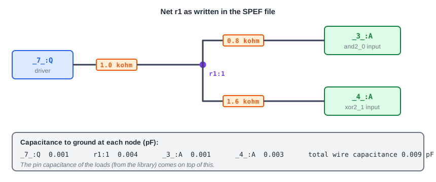
This is the net r1 of the demo circuit, written as a SPEF file for this tutorial. The same net is drawn above:
*SPEF "IEEE 1481-1998"
*DESIGN "sta_demo"
*DESIGN_FLOW "PIN_CAP NONE" "NAME_SCOPE LOCAL"
*DIVIDER /
*DELIMITER :
*T_UNIT 1 NS
*C_UNIT 1 PF
*R_UNIT 1 KOHM

*D_NET r1 0.009
*CONN
*I _7_:Q O
*I _3_:A I
*I _4_:A I
*CAP
1 _7_:Q 0.001
2 r1:1 0.004
3 _3_:A 0.001
4 _4_:A 0.003
*RES
1 _7_:Q r1:1 1.0
2 r1:1 _3_:A 0.8
3 r1:1 _4_:A 1.6
*END
The file has a header and one block for every net:
- The header sets the units. Here, time is in ns, capacitance in pF and resistance in kilo-ohm. Always check the units, because a wrong unit changes every delay by a large factor.
*D_NET r1 0.009starts the netr1. The number is its total capacitance in pF.*CONNlists the pins of the net.Omarks the driver andIthe loads. The pin name_7_:Qmeans the pinQof the cell_7_.*CAPlists the capacitors to ground, one per node. Nodes named liker1:1are points inside the wire that are not cell pins.*RESlists the resistors, each between two nodes.
The capacitances add up to 0.001 + 0.004 + 0.001 + 0.003 = 0.009 pF, which is the total in the first line. The setting PIN_CAP NONE in the header says that the capacitance of the cell pins is not included in the file. The tool takes it from the library, so the load of the driver is the 0.009 pF of wire plus the pin capacitances of the two loads.
Real files contain two more details. First, a capacitor between two nets, called a coupling capacitor, is written with two node names in the *CAP section. It is the basis of the crosstalk analysis in a later chapter. Second, long names are often replaced by short numbers listed in a name map at the top of the file, so that the file is smaller.
What the Tool Does with It
With the parasitics read, a net has two effects on timing. The total capacitance is part of the load that the driving cell sees. The resistors delay the signal on its way from the driver to each load, so every load pin has its own net delay. Here is the net report of r1 and the path through it:
Net r1
 Pin capacitance: 0.0058-0.0062
 Wire capacitance: 0.0090
 Total capacitance: 0.0148-0.0152
 Number of loads: 2

      Cap      Slew     Delay      Time   Description
   0.0148    0.0787    0.3069    0.3069 v _7_/Q (sky130_fd_sc_hd__dfxtp_1)
             0.0908    0.0234    0.3304 v _4_/A (sky130_fd_sc_hd__xor2_1)
   0.0017    0.0474    0.1653    0.4957 v _4_/X (sky130_fd_sc_hd__xor2_1)
The line _4_/A is new. It is the net delay of 0.0234 ns from the driver to the load pin. The other load _3_/A has a shorter wire and gets 0.0160 ns. Two loads on the same net can have different arrival times, which a wire load model cannot show. Also note that the slew grows from 0.0787 ns at the driver to 0.0908 ns at the load, because the wire rounds the edge.
SPEF Compared with a Wire Load Model
For the same path, the slack is 1.4502 ns with no wires, 1.3785 ns with the example wire load model and 1.3822 ns with this SPEF. The two estimates are close here by chance. They are made in very different ways: the model assumed 0.0060 pF for the net, while the SPEF has 0.0090 pF and, in addition, a delay inside the wire. In a real design the difference can be large in either direction, which is why the layout data replaces the estimate.
Common Mistakes
Mistake #1: Ignoring the units in the SPEF header
The capacitance and resistance units come from the header. A file in fF read as pF, or kilo-ohm read as ohm, gives delays that are wrong by a factor of 1000. Check that the units agree with the library before trusting any result.
Mistake #2: Adding the pin capacitance twice
The header setting tells whether the file already includes the capacitance of the cell pins. If it says PIN_CAP NONE, the tool adds the pins from the library. If the file also contained them, the load would be counted twice.
Quick Check: A net in a SPEF file has node capacitances of 0.002, 0.005 and 0.003 pF. What should the total in its *D_NET line be?
The total is the sum of all capacitors to ground: 0.002 + 0.005 + 0.003 = 0.010 pF. Coupling capacitors to other nets, if the net has any, are part of the total too.
Practice Exercise
Challenge: What Does a Lumped Capacitor Miss?
The lab does not read a SPEF file, but you can replace the wire of a net with a single capacitor that has the same total value. Run the sta_demo design, then add this line to constraints.sdc, which gives the net r1 the 0.009 pF of the SPEF above:
set_load 0.009 [get_nets r1]
Look at the path from _7_ to _6_. The SPEF run had a clock-to-Q delay of 0.3069 ns, a net delay of 0.0234 ns and a data arrival time of 0.4957 ns. Which of these three numbers can the lumped capacitor reproduce?
Open the ready-made example in the lab, run synthesis, and then run STA. Editing constraints.sdc and re-running only STA, and choosing another library or corner, are PRO features.
Hint
A single capacitor has no resistance. Think about which effect of the wire needs a resistor.
Solution
The load on _7_/Q is now 0.0148 pF, the same as with the SPEF, but there is no net delay line at all, because without a resistor the signal arrives at the load at the same moment it leaves the driver. The data arrival time is 0.4806 ns instead of 0.4957 ns, so the slack is 1.3977 ns instead of 1.3822 ns. The lumped capacitor gives an optimistic result because it misses the delay inside the wire. The clock-to-Q delay is also different: 0.3206 ns instead of 0.3069 ns. The reason is explained in Effective Capacitance.
Summary
- Extraction measures the resistance and capacitance of every wire from the layout and stores them in a SPEF file.
- A net becomes an RC tree: resistors along the wire and capacitors to ground at the nodes.
- In SPEF,
*D_NETstarts a net,*CONNlists pins,*CAPthe capacitors and*RESthe resistors. - The header sets the units and tells whether pin capacitance is already included.
- The capacitance changes the load of the driver. The resistance adds a net delay and degrades the slew at each load pin.
- A single lumped capacitor can model the load but not the delay inside the wire.
