
After synthesis, the design goes to physical implementation. Placement puts every cell at a place on the chip, and clock tree synthesis builds the network that delivers the clock to every flip-flop. Both steps change timing: placement fixes the distances, and the clock tree creates skew and a real clock latency. This article explains what happens to timing in each of the two steps, shows the effect of the clock tree with real numbers, and says why hold fixing comes after it.
8 min read | Intermediate
What You'll Learn
- Describe what the placement tool does with timing information
- Explain what clock tree synthesis builds and what it tries to achieve
- Read the change of setup and hold slack when the clock changes from ideal to propagated
- Say why hold violations are fixed after the clock tree is built
Timing in Placement
Placement decides where each cell sits. The tool has a timing engine and uses it to place the cells of critical paths close together, so that their wires are short. It estimates the wire delay from the positions, for example with a simple model of the length of the wire, and updates the slack as cells move. Typical actions during placement are:
- Moving the cells of a critical path next to each other, and away from the cells of paths that have plenty of slack.
- Sizing cells and adding buffers, as the synthesis tool did, now with a better idea of the wires.
- Splitting nets with a large fanout.
- Avoiding congestion, because a crowded area forces long detours of the wires.
At this stage the clocks are still ideal. The tool assumes that all flip-flops get their clock at the same moment, and it optimizes the data paths. The wire estimates are better than a wire load model, but they are not the final routes.
Clock Tree Synthesis
A clock net can have thousands of flip-flop pins. One driver cannot drive them all with a sharp edge, and the wires have different lengths. Clock tree synthesis builds a tree of buffers from the clock port to the flip-flops. The goals are:
- A small skew between flip-flops that exchange data. The tool balances the delay of the branches.
- A good edge, with a slew that is within the limits, at every clock pin.
- A small area and power. Clock buffers use a large part of the dynamic power of a chip.
- Robustness against variation, which means that the branches share as much of the path as possible.
The tree gets its delay by itself. The clock now arrives later at the flip-flops, by the latency of the tree, and different flip-flops get it at slightly different times.
What Changes in the Report
Before the tree, the clock is ideal. After it, the clock is propagated, which means STA follows the buffers of the tree, as in the article about clock latency. The tree of that article has a root buffer and two branches, with the clock arriving at 0.1701 ns at the first flip-flop and at 0.2435 ns at the second:
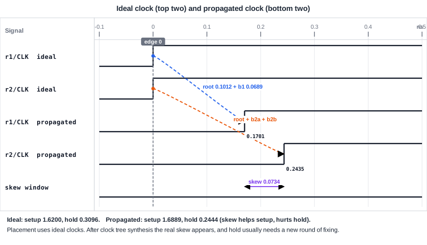
| Clock | Setup slack (ns) | Hold slack (ns) |
|---|---|---|
| ideal (placement) | 1.6200 | 0.3096 |
| propagated (after clock tree) | 1.6889 | 0.2444 |
The skew of 0.0734 ns, with the capture clock later, gives setup 0.07 ns more and hold 0.07 ns less. This is the usual pattern: a clock tree changes hold more than setup, because skew moves both in opposite directions and hold has a smaller margin to begin with. In a real design, a skew of 0.1 ns can be enough to make hold fail for a pair of flip-flops with a short path between them.
Why Hold Fixing Comes After the Tree
Before the tree exists, the clock skew is unknown. The hold slack that the tool sees with ideal clocks is not the one that the chip will have. If the tool tried to fix hold at that point, it would add delay cells where no real violation exists, and it would miss the places where the tree creates one. The usual order is:
- Place the cells and optimize setup with ideal clocks.
- Build the clock tree.
- Switch to propagated clocks, check setup again, and fix hold with delay cells and sizing, as in the article about fixing hold violations.
- Route the wires, extract the parasitics, and repeat the checks and the fixes with the real wires and with crosstalk.
The fixing of hold costs area and some setup slack, as shown in that article. Teams try to keep the skew small so that the number of fixes stays low.
Useful Skew in the Flow
Some clock tree tools can build the tree with an intended skew, using the delay of the capture clock to help a failing path. This is the useful skew of the article about clock skew, and the tool checks that the hold slack and the neighbouring paths stay positive.
Common Mistakes
Mistake #1: Reading the hold slack before the clock tree as a result
With ideal clocks, the hold slack of a path between two flip-flops looks like the delay of the first flip-flop. The tree can remove a part of it, and the real result appears only afterwards.
Mistake #2: Keeping ideal-clock constraints after the tree
If a clock latency or an uncertainty for the missing tree is still in the constraints, the result does not follow the real tree, as explained in the article about clock latency. Remove the estimates when the tree is there.
Quick Check: After the clock tree, the capture flip-flop receives the clock 0.05 ns later than the launch flip-flop. How do the setup and hold slack of the path between them change?
The setup slack increases by 0.05 ns and the hold slack decreases by 0.05 ns.
Practice Exercise
Challenge: Predict the Effect of the Tree
Use the sta_demo design with ideal clocks. The setup slack of the path from _7_ to _6_ is 1.4502 ns and the hold slack is 0.4241 ns. Emulate a clock tree that delivers the clock to the capture flip-flop 0.0734 ns later than to the launch flip-flop:
set_clock_latency 0.0734 [get_pins _6_/CLK]
Predict the two slacks and say which check is in danger if the skew grows to 0.45 ns.
Open the ready-made example in the lab, run synthesis, and then run STA. Editing constraints.sdc and re-running only STA, and choosing another library or corner, are PRO features.
Hint
Setup gains the skew and hold loses it. The hold slack has less margin.
Solution
The setup slack becomes 1.4502 + 0.0734 = 1.5236 ns and the hold slack becomes 0.4241 - 0.0734 = 0.3507 ns. With a skew of 0.45 ns the hold slack is 0.4241 - 0.45 = -0.0259 ns, a violation, while the setup slack would be 1.9 ns. Hold is the check in danger.
Summary
- Placement puts the cells of critical paths close together and uses a timing engine to guide the choices, still with ideal clocks.
- Clock tree synthesis builds a buffer tree that delivers the clock to all flip-flops with a small skew and a good edge.
- After the tree, the clock is propagated, and the real skew appears in the slack.
- In the example tree, the skew of 0.0734 ns changes the setup slack from 1.6200 ns to 1.6889 ns and the hold slack from 0.3096 ns to 0.2444 ns.
- Hold is fixed after the tree, because only then is the real skew known.
- Remove clock estimates from the constraints once the tree exists.
