
Fast interfaces between chips often send the clock together with the data, instead of using a common clock. This is called a source-synchronous interface. Some of them send a new data value on both edges of the clock, the double data rate (DDR). For STA, the main change is in the input and output delays: they now refer to both clock edges, and each half cycle is a separate check. This article shows how to constrain a DDR input and what the slacks mean.
9 min read | Intermediate
What You'll Learn
- Explain what a source-synchronous and a DDR interface are
- Constrain a DDR input with
-clock_falland-add_delay - Calculate the setup and hold slack of each half of a DDR input
- See why the timing budget of a DDR interface is half of that of a single data rate interface
Source Synchronous Interfaces
In a source-synchronous interface, the chip that sends the data also sends a clock that travels along with the data over the same kind of wires. The receiving chip uses this clock to capture the data. Because clock and data take similar paths, the differences between chips and boards matter less, and the clock can be fast.
For STA of the receiving chip, the clock of the interface comes in at a port, and the data arrives at other ports with a known relation to it. The relation is given by the datasheet of the sender, as an input delay for the data with respect to the clock.
Double Data Rate
In a DDR interface, the data changes on both clock edges. One value is launched on the rising edge, and the next one on the falling edge. In the receiver, one flip-flop captures on the rising edge and another on the falling edge:
module sta_ddr (input clk, d, output q0, q1);
  reg rp, rn;
  always @(posedge clk)
    rp <= d;                          // captures the values sent on the falling edge
  always @(negedge clk)
    rn <= d;                          // captures the values sent on the rising edge
  assign q0 = rp;
  assign q1 = rn;
endmodule
The clock has a period of 2.0 ns, and each value is stable for 1.0 ns. The shorter time of a half cycle is the main reason why DDR interfaces are harder to close than single data rate interfaces.
Describing the Two Launch Edges
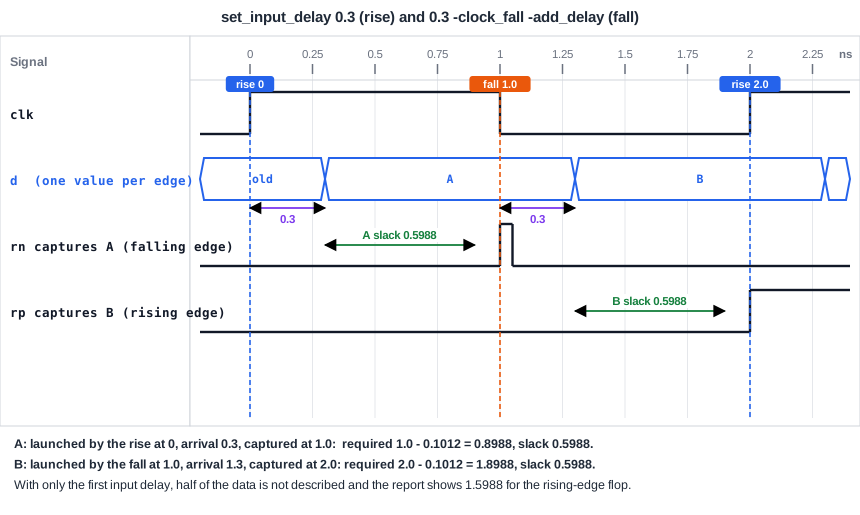
A single set_input_delay says that the data is launched on the rising edge of the clock. For the values that are launched on the falling edge, you add a second command with -clock_fall and -add_delay:
create_clock -name clk -period 2.0 [get_ports clk]
set_input_delay 0.3 -clock clk [get_ports d]
set_input_delay 0.3 -clock clk -clock_fall -add_delay [get_ports d]
set_output_delay 0.2 -clock clk [get_ports {q0 q1}]
- The first command: data launched by the rising edge, 0.3 ns after it.
- The second command: data launched by the falling edge, 0.3 ns after it.
-clock_fallsays that the delay refers to the falling edge.-add_delaykeeps the first command. Without it, the second one replaces the first.
Quick Check
Q: What happens if the second set_input_delay of a DDR input is written without -add_delay?
Show Answer
It replaces the first one. Only the falling-edge data is described, and the paths of the data launched on the rising edge are no longer checked.
The Results
With only the first command, the rising-edge flip-flop rp (the cell _3_ in our run) has a setup slack of 1.5988 ns: it captures data that was launched by the rising edge, and it has a full period. The falling-edge flip-flop rn (_2_) has a setup slack of 0.5988 ns, because the rising-edge data has only half of a period until the falling edge. The data launched by the falling edge is not described at all, so the second half is not checked.
max_delay/setup group clk
_2_/D (sky130_fd_sc_hd__dfxtp_1)        0.8988    0.3000    0.5988 (MET)
With the second command, both launch edges are described, and both flip-flops show 0.5988 ns of setup slack:
max_delay/setup group clk

Endpoint                                 Delay     Delay     Slack
_2_/D (sky130_fd_sc_hd__dfxtp_1)        0.8988    0.3000    0.5988 (MET)
_3_/D (sky130_fd_sc_hd__dfxtp_1)        1.8988    1.3000    0.5988 (MET)

min_delay/hold group clk
_2_/D (sky130_fd_sc_hd__dfxtp_1)        0.9723    1.3000    0.3277 (MET)
_3_/D (sky130_fd_sc_hd__dfxtp_1)       -0.0277    0.3000    0.3277 (MET)
Look at the two endpoints. The falling-edge flip-flop _2_ captures at 1.0 ns, which is 1.0 - 0.1012 = 0.8988 ns after the setup time, and the data launched at 0 arrives at 0.3 ns. The rising-edge flip-flop _3_ captures at 2.0 ns, which is 2.0 - 0.1012 = 1.8988 ns, and the data launched by the falling edge at 1.0 ns arrives at 1.3 ns. Each capture has a window of 1.0 ns minus the delay and the setup time, which is 0.5988 ns.
The hold slack is 0.3277 ns for both, and for the same reason: each half cycle is checked against the capture edge of its own half.
Quick Check
Q: A DDR interface has a clock period of 4.0 ns and an input delay of 0.5 ns. What is the time window of each half cycle, before the setup time?
Show Answer
Each value lasts half of the period, 2.0 ns. After the input delay of 0.5 ns, 1.5 ns remain for the setup time and the logic.
What Would Go Wrong With One Command
With only the rising-edge input delay, the design appears to have a setup slack of 1.5988 ns on _3_/D. This number would be fine if the interface were single data rate. For a DDR interface it hides the second half, the data that was launched by the falling edge, which has 0.5988 ns. The constraints must describe all the data that really arrives, or the report tells you less than you need.
Output DDR
For an output that sends data on both edges, the same pair of options is used with set_output_delay. One command is for the receiver that captures on the rising edge, and a second one with -clock_fall -add_delay for the receiver that captures on the falling edge. A source-synchronous output also needs the clock to be output with the data. That is described with a generated clock on the output port, using the clock of the chip as the master.
Common Mistakes
Mistake #1: Forgetting -add_delay
Without it, the second set_input_delay overwrites the first one. The design then has only the falling-edge description, and the rising-edge half is not checked.
Mistake #2: Constraining a DDR interface like a single data rate one
A single delay gives a clean report that does not cover half of the data. Check that every capture flip-flop of the interface has a path in the report, from the rising edge and from the falling edge.
Practice Exercise
Challenge: Cover Both Edges
Paste the sta_ddr design into the lab with the clock, the output delays and only the first set_input_delay. Note the setup slack of the two capture flip-flops. Then add the falling-edge input delay with -clock_fall -add_delay and compare.
Hint
Count the endpoints in the setup summary. One of the flip-flops changes its worst path.
Solution
With one command, the rising-edge flip-flop has a setup slack of 1.5988 ns and the falling-edge flip-flop has 0.5988 ns. After adding the second command, the rising-edge flip-flop shows 0.5988 ns, the slack of the data that is launched by the falling edge, which is the worst of its paths. The hold slack of the falling-edge flip-flop falls from 1.3277 ns to 0.3277 ns, because the data launched by the falling edge is now checked against it as well. The numbers of the lab can differ in the last digit.
Open the ready-made example in the lab, run synthesis, and then run STA. Editing constraints.sdc and re-running only STA, and choosing another library or corner, are PRO features.
Summary
- A source-synchronous interface sends the clock with the data. A DDR interface changes the data on both clock edges.
- The input delay of a DDR interface is given twice: once for the rising edge, and once with
-clock_fall -add_delayfor the falling edge. - Each value is stable for half of a period, so each capture has a window of half a period minus the delay and the setup time.
- With a period of 2.0 ns and a delay of 0.3 ns, both captures have a setup slack of 0.5988 ns.
- With only one input delay, half of the data is not described, and the report looks better than the interface is.
- Output DDR uses the same options with
set_output_delay.