
Wires that run next to each other are coupled by a small capacitor between them. When one wire switches, it pushes on its neighbour. This changes the delay of the neighbour and can even create a false pulse on it. These effects are called signal integrity, and in modern chips they are a real part of timing. This chapter covers what STA can do about them.
Crosstalk delay is the change of a signal delay that is caused by the switching of a neighbouring signal. It can make a path slower or faster than the analysis without coupling. This article explains the two cases, speed-up and slow-down, shows them on the demo circuit with real numbers, and says which one is used for setup and which one for hold.
9 min read | Intermediate
What You'll Learn
- Define victim, aggressor and coupling capacitance
- Explain why the neighbour can slow down or speed up the victim
- Say which crosstalk case is the worst for setup and for hold
- Estimate the effect of crosstalk by changing the coupling capacitance in a parasitic file
Victim, Aggressor, Coupling
Two wires that run side by side form a capacitor between them. The wire whose delay we want to know is the victim. The neighbour that switches is the aggressor. In the parasitics, this capacitor is written as a coupling capacitance between two nets. Until now the examples used only capacitors between a net and the ground, and a coupling capacitor was treated as part of the capacitance to ground.
Whether the coupling capacitor hurts depends on what the aggressor does while the victim switches. The voltage across the capacitor determines how much charge the victim driver has to move.
- The aggressor is quiet. The capacitor behaves as a capacitor to ground. This is the reference case.
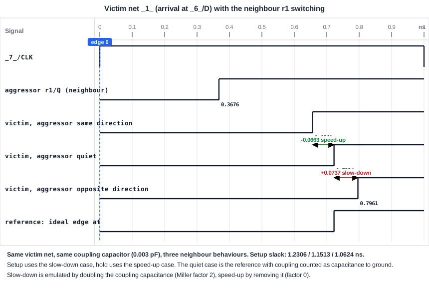
- The aggressor switches in the opposite direction. The voltage across the coupling capacitor changes by twice as much, so the victim driver has to move about twice the charge of the capacitor. The victim is slowed down. This case is called a slow-down, and the capacitor acts as if it were about twice as large. This factor is the Miller factor of 2.
- The aggressor switches in the same direction. The voltage across the capacitor hardly changes, so the victim does not need to charge it. The victim is speeded up. The capacitor acts as if it were almost absent, a Miller factor of about 0.
An Example
In the demo circuit, the net r1 from the first flip-flop and the net _1_ from the XOR gate to the second flip-flop are coupled by 0.003 pF. The net _1_ is the victim, and r1 is the aggressor. The parasitic file has the coupling capacitor in the capacitance sections of both nets. OpenSTA reads it with read_spef and the option -coupling_reduction_factor, which multiplies the coupling capacitance before it is added to the capacitance to ground:
read_spef -coupling_reduction_factor 1.0 xt.spef    # coupling counted as ground capacitance
read_spef -coupling_reduction_factor 0.0 xt.spef    # coupling ignored
A factor of 1.0 gives the quiet case. A factor of 0.0 removes the coupling and stands for the speed-up case. For the slow-down, the same effect is made by doubling the coupling capacitance in the file, 0.006 pF instead of 0.003 pF, and reading it with the factor 1.0. The arrival time at the data pin of the second flip-flop, and the setup slack of the path, are:
| Neighbour | Coupling as seen by the victim | Arrival at _6_/D (ns) | Setup slack (ns) | Hold slack (ns) |
|---|---|---|---|---|
| same direction (speed-up) | 0 (removed) | 0.6561 | 1.2306 | 0.5946 |
| quiet | 0.003 pF to ground | 0.7224 | 1.1513 | 0.6434 |
| opposite direction (slow-down) | 0.006 pF to ground | 0.7961 | 1.0624 | 0.6998 |
The arrival time moves from 0.6561 ns to 0.7961 ns, a spread of 0.14 ns, caused only by what the neighbour does. For the setup check the worst case is the slow-down: the slack is 1.0624 ns. For the hold check the worst case is the speed-up, because the data arrives earliest: the hold slack is 0.5946 ns. The same coupling capacitor creates one worst case for each of the checks.
How STA Uses It
- For setup, the victim's delay is calculated with the slow-down assumption for the nets that have an aggressor. The data path is slower.
- For hold, it is calculated with the speed-up assumption. The data path is faster.
- A real tool does this per net, and it adds a delay (a delta delay) to the net delay of the victim.
Treating every neighbour as if it were switching at the worst moment is very pessimistic, because most neighbours do not switch at the same time as the victim. The article about timing windows and aggressor alignment explains how the pessimism is reduced.
Where It Matters
Crosstalk delay gets worse with the technology. Wires get thinner and closer together, so the coupling capacitance is a larger part of the total, in modern technologies more than half. Long parallel wires, clock nets and wires on the same layer are the most exposed. Clock nets also suffer: crosstalk on a clock net moves the clock arrival time, which changes the skew.
Common Mistakes
Mistake #1: Signing off without crosstalk
A parasitic extraction that holds the coupling capacitors, with a timing analysis that ignores them, can give setup and hold slacks that are wrong in the optimistic direction. At the sign-off, the analysis has to include crosstalk delay.
Mistake #2: Using the speed-up case for setup
The slow-down gives the worst setup and the speed-up gives the worst hold. Using the quiet case for both is optimistic on both sides.
Quick Check: Which neighbour behaviour is the worst for the hold check of a victim net, and why?
The neighbour that switches in the same direction, because it speeds up the victim and makes its data arrive earlier.
Practice Exercise
Challenge: Work Out the Spread
This is a pencil and paper exercise with the table above. The arrival times at the data pin are 0.6561 ns (speed-up), 0.7224 ns (quiet) and 0.7961 ns (slow-down). Calculate the delay change of the slow-down and of the speed-up relative to the quiet case, and the setup slack of the slow-down if the required time is 1.8585 ns.
Hint
The change is the difference of the two arrival times. The slack is required minus arrival.
Solution
The slow-down adds 0.7961 - 0.7224 = 0.0737 ns. The speed-up removes 0.7224 - 0.6561 = 0.0663 ns. The setup slack with the slow-down is 1.8585 - 0.7961 = 1.0624 ns, which agrees with the table.
Summary
- Neighbouring wires are coupled by a capacitor. The wire that is analyzed is the victim, and the neighbour that switches is the aggressor.
- An aggressor that switches in the opposite direction slows the victim down, as if the coupling capacitor were about twice as large.
- An aggressor that switches in the same direction speeds the victim up, as if the capacitor were absent.
- In the demo circuit, the arrival time moves between 0.6561 ns and 0.7961 ns, depending on the neighbour.
- Setup uses the slow-down and hold uses the speed-up.
- Assuming that every neighbour switches at the worst time is pessimistic, and timing windows reduce the pessimism.
