
A real project starts with a specification, not with a clock period. For a UART transmitter the specification says: the chip clock is 100 MHz, the output sends 115200 bits per second, and the data comes from a controller that is clocked by the same clock. Writing the SDC for it means turning those sentences into constraints, one port at a time. This article builds the SDC for a UART transmitter and shows, with real reports, what each line changes and what happens when a line is missing.
10 min read | Intermediate
What You'll Learn
- Turn a design specification into a clock, input delays, output delays and load values
- Choose the delays at the ports from the timing budget of the neighbouring blocks
- Show with
check_setupand a report that a missing constraint hides violations - Read the separate path groups of a design with asynchronous resets
The Design
The UART transmitter takes a start pulse and 8 data bits, and sends them as one serial frame: a start bit (low), 8 data bits starting with the least significant one, and a stop bit (high). A counter divides the clock down to one tick per bit. At 100 MHz and 115200 baud, one bit lasts 100,000,000 / 115,200 = 868.06, which is 868 clock cycles when rounded to a whole number, so the counter counts from 0 to 867.
module uart_tx (
  input        clk,
  input        rst_n,
  input        start,
  input  [7:0] data,
  output reg   tx,
  output       busy
);
  localparam DIV = 10'd867;            // 100 MHz / 115200 baud
  reg [9:0] cnt;
  reg [3:0] bit_idx;
  reg [7:0] shreg;
  reg       active;
  wire tick = (cnt == DIV);
  assign busy = active;
  always @(posedge clk or negedge rst_n) begin
    if (!rst_n) begin
      cnt <= 10'd0;
      bit_idx <= 4'd0;
      shreg <= 8'd0;
      active <= 1'b0;
      tx <= 1'b1;
    end
    else begin
      if (!active) begin
        cnt <= 10'd0;
        tx <= 1'b1;
        if (start) begin
          active <= 1'b1;
          shreg <= data;
          bit_idx <= 4'd0;
          tx <= 1'b0;
        end
      end
      else begin
        cnt <= tick ? 10'd0 : cnt + 10'd1;
        if (tick) begin
          if (bit_idx == 4'd8) begin
            tx <= 1'b1;
            bit_idx <= bit_idx + 4'd1;
          end
          else if (bit_idx == 4'd9) begin
            active <= 1'b0;
          end
          else begin
            tx <= shreg[0];
            shreg <= {1'b0, shreg[7:1]};
            bit_idx <= bit_idx + 4'd1;
          end
        end
      end
    end
  end
endmodule
The design has one clock, one asynchronous reset rst_n, and two groups of ports: the inputs start and data[7:0], and the outputs tx and busy. This list is the checklist for the SDC. Every port must be covered.
Quick Check
Q: A UART outputs 115200 bits per second and is clocked at 50 MHz. What is the divider value?
Show Answer
The number of clock cycles per bit is 50,000,000 / 115,200 = 434 (rounded from 434.03), so the counter counts from 0 to 433.
Step 1: The Clock
The specification says 100 MHz, so the period is 10 ns:
create_clock -name clk -period 10 [get_ports clk]
The clock is defined on the port, and it is ideal: the constraint says nothing about the delay of the clock tree, because the tree does not exist yet. This is the correct assumption before clock tree synthesis, and the later articles on clocks explain how it changes afterwards.
What Happens With the Clock Only
Run the design with only this line and ask for the missing constraints:
Warning: There are 10 input ports missing set_input_delay.
  data[0]
  data[1]
  ...
  data[7]
  rst_n
  start
Warning: There are 2 output ports missing set_output_delay.
  busy
  tx
Warning: There are 2 unconstrained endpoints.
  busy
  tx
The report of the setup paths then shows only the paths between flip-flops, and the worst slack is 8.2477 ns. It looks like a healthy design. It is not a result you can use: the paths from the inputs and to the outputs were not checked at all. When the input delay is added in the next step, the worst slack becomes 7.0819 ns, a smaller number, because a real path from an input was added. A missing constraint can only hide violations, never create them.
Quick Check
Q: Adding the input delays made the worst setup slack smaller, from 8.2477 to 7.0819 ns. Did the design get slower?
Show Answer
No. The cells are the same. The input delays added the paths from the input ports to the checks, and one of them is tighter than any path between flip-flops. The first number was too good because those paths were not checked.
Step 2: Input Delays
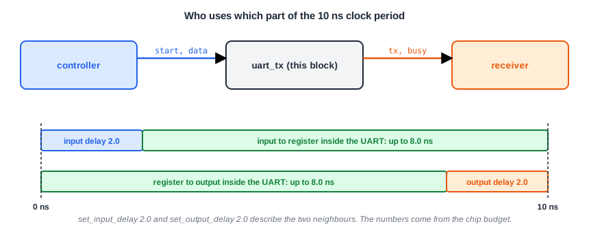
An input delay tells STA how much of the clock period the outside world has already used. The signals start and data come from a controller that runs on the same clock. In the system, the controller output has a clock-to-Q delay and some wire, so we assume the data arrives 2 ns after the clock edge, leaving 8 ns for the logic inside the UART:
set_input_delay 2.0 -clock clk [get_ports {rst_n start data*}]
The number 2.0 is not a property of the UART. It is a part of the budget of the whole chip, agreed with the team that designs the controller (the article about input and output delays explains how it is chosen). If the controller is slower than the budget, the timing of this block will be wrong even if its own report is clean. The reset port is included for now, and a later article will show why that needs a second look.
Step 3: Output Delays
The same budget holds for the outputs. The receiver on the other side needs the signals 2 ns before its own clock edge, for its setup time and its wires:
set_output_delay 2.0 -clock clk [get_ports {tx busy}]
With these two lines, check_setup -verbose prints nothing, and every port is covered.
Step 4: Clock Uncertainty and the Port Environment
Two more groups of commands make the numbers closer to real hardware. The uncertainty takes a margin from every setup check for the jitter of the clock and for the tolerance of the early estimates. The input transition says how sharp the edges that come from outside are, and the load says how much capacitance the output pins have to drive:
set_clock_uncertainty 0.2 [get_clocks clk]
set_input_transition 0.2 [get_ports {rst_n start data*}]
set_load 0.05 [get_ports {tx busy}]
The complete file for the UART is these lines together with the clock and the delays, six lines in all:
create_clock -name clk -period 10 [get_ports clk]
set_clock_uncertainty 0.2 [get_clocks clk]
set_input_delay 2.0 -clock clk [get_ports {rst_n start data*}]
set_input_transition 0.2 [get_ports {rst_n start data*}]
set_output_delay 2.0 -clock clk [get_ports {tx busy}]
set_load 0.05 [get_ports {tx busy}]
What the Report Shows
With the complete SDC, the output port tx is driven directly by a flip-flop. This is its report:
Startpoint: _141_ (rising edge-triggered flip-flop clocked by clk)
Endpoint: tx (output port clocked by clk)
Path Group: clk
Path Type: max

      Cap      Slew     Delay      Time   Description
-------------------------------------------------------------------------------
             0.0000    0.0000    0.0000   clock clk (rise edge)
                       0.0000    0.0000   clock network delay (ideal)
             0.0000    0.0000    0.0000 ^ _141_/CLK (sky130_fd_sc_hd__dfstp_2)
   0.0525    0.2618    0.6638    0.6638 ^ _141_/Q (sky130_fd_sc_hd__dfstp_2)
             0.2618    0.0000    0.6638 ^ tx (out)
                                 0.6638   data arrival time

             0.0000   10.0000   10.0000   clock clk (rise edge)
                       0.0000   10.0000   clock network delay (ideal)
                      -0.2000    9.8000   clock uncertainty
                       0.0000    9.8000   clock reconvergence pessimism
                      -2.0000    7.8000   output external delay
                                 7.8000   data required time
-------------------------------------------------------------------------------
                                 7.8000   data required time
                                -0.6638   data arrival time
-------------------------------------------------------------------------------
                                 7.1362   slack (MET)
Find the numbers that come from the SDC. The required time is 10.0 minus the uncertainty of 0.2 minus the output delay of 2.0, which is 7.8 ns. The load of 0.05 pF on the output makes the flip-flop slower: its clock-to-Q delay is 0.6638 ns and its slew is 0.2618 ns, because it drives 0.0525 pF. The slack of 7.1362 ns is large, because the output is directly after a register.
An input path shows the other side of the budget. For data[3], the path is the input delay of 2.0 ns, an AND gate (0.1908 ns) and an a221o gate (0.2447 ns), arriving at the data pin at 2.4355 ns. The required time is 10.0 - 0.2 - 0.1260 (setup time) = 9.6740 ns, so the slack is 7.2384 ns.
Path Groups
The report of the whole design has a section for each path group. The flip-flops with an asynchronous reset have an extra check, between the reset port and the reset pin, and OpenSTA prints it in its own group:
| Group | Check | Worst endpoint | Slack (ns) |
|---|---|---|---|
| clk | setup | _133_/D | 6.8285 |
| asynchronous | recovery (setup of the reset) | _141_/SET_B | 7.9083 |
| clk | hold | _146_/D | 0.2542 |
| asynchronous | removal (hold of the reset) | _133_/RESET_B | 1.4493 |
The recovery and removal checks are explained in the article about recovery and removal. They are the setup and hold checks of the reset release. Notice that the removal slack, 1.4493 ns, is the smallest of the asynchronous numbers and it is already getting small. The next articles use a much faster clock, and it is this check that fails first.
Common Mistakes
Mistake #1: Constraining only the clock
A design with only a clock has a good-looking worst slack because the paths at the ports are not checked. Constrain every input and every output, and check with check_setup -verbose.
Mistake #2: Choosing the port delays to make the report pass
The input and output delays are the share of the clock period that belongs to the neighbouring blocks. If you set them to zero to get a better slack, the block passes on paper and fails in the chip, where the neighbours do use their share.
Practice Exercise
Challenge: Cover Every Port
Paste the UART and the SDC of this article into the lab. Run check_setup -verbose, then remove the line set_output_delay and run it again. Which ports are reported? Then remove only the input delay of the reset (use {start data*} in the input delay line) and look at the asynchronous group of the report.
Hint
A path that has no constraint at one end is not checked. Look at which checks have disappeared from the report.
Solution
Without the output delay, check_setup reports that tx and busy are missing an output delay and are unconstrained endpoints, and the path to tx no longer appears. Without the reset input delay, rst_n is reported as missing an input delay, and the recovery and removal checks of the reset disappear from the asynchronous group, even though the real reset still has to meet them.
Open the ready-made example in the lab, run synthesis, and then run STA. Editing constraints.sdc and re-running only STA, and choosing another library or corner, are PRO features.
Summary
- The SDC of a block comes from its specification: the clock period from the clock frequency, and the port delays from the budget of the neighbouring blocks.
- A UART at 100 MHz and 115200 baud needs a divider of 868 clock cycles per bit.
- With only the clock defined, the worst slack of the UART looks like 8.2477 ns. With the port delays it is 7.0819 ns. Missing constraints hide paths.
- The uncertainty, input transition and load make the numbers closer to the real chip. The complete UART SDC has six lines.
- OpenSTA prints the reset checks (recovery and removal) in an asynchronous path group, separate from the paths of the clock.
- With the complete SDC at 10 ns, the worst setup slack is 6.8285 ns and the worst hold slack is 0.2542 ns.
