
In the timing graph, every cell contributes arcs. In the Liberty file, each of those arcs is written as a timing () group. This article reads those groups: what a group names, which kinds of arc exist, and how the library describes cells whose output direction depends on the other inputs, such as an XOR gate.
In the subway-map picture from Timing Graphs and Arcs, every rail line between two stations is an arc. The Liberty file is where each of those lines is written down, with its travel times.
7 min read | Intermediate
What You'll Learn
- Read the three identifying fields of a Liberty timing group
- Recognize the common timing types: combinational, rising edge, setup, hold and pulse width
- Explain how a library models a non-unate cell with two arcs
- Predict which arc STA uses for a setup check and for a hold check
Anatomy of a Timing Group
A timing group sits inside the output pin it describes. Three fields say which arc it is, and four tables hold the numbers:
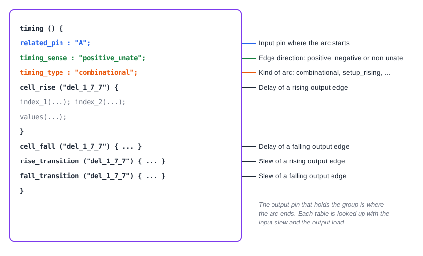
related_pinis the pin where the arc starts. The output pin that holds the group is where it ends.timing_sensesays how the output edge relates to the input edge:positive_unate,negative_unateornon_unate.timing_typesays what kind of arc it is. If it is left out, the arc is a normal combinational delay.
The two unate cases and the non-unate case were introduced in Timing Graphs and Arcs. In the library the counts show how common each is: the high-density library has 668 positive unate, 604 negative unate and 91 non-unate arcs.
Timing Types
The timing_type separates delay arcs from timing checks. These are the ones you meet most often:
| timing_type | Where it appears | What it describes |
|---|---|---|
| combinational | output of a gate | Delay from an input to the output. This is the default. |
| rising_edge, falling_edge | Q pin of a flip-flop | Delay from the active clock edge to the output (clock-to-Q). |
| setup_rising, setup_falling | data pin of a flip-flop | Setup time: how early data must be stable before the clock edge. |
| hold_rising, hold_falling | data pin of a flip-flop | Hold time: how long data must stay stable after the clock edge. |
| min_pulse_width | clock pin | The shortest allowed high or low time of the clock. |
| recovery_rising, removal_rising | reset or set pin | Timing checks for an asynchronous reset release, covered in a later chapter. |
| clear, preset | Q pin | Delay from an asynchronous clear or preset to the output. |
| three_state_enable, three_state_disable | tri-state output | Delay to turn the output on or off. |
The words rising and falling in the names refer to the clock edge that the check or the delay is relative to. Setup and hold arcs are the timing check arcs from the graph article. Their data are requirements, not delays, and they are the subject of the article on sequential cells.
A Cell With Two Arcs: the XOR Gate
An AND gate has one arc from each input. Its sense is positive unate, whatever the other input does. An XOR gate is different. If input A rises, the output rises when B is 0 and falls when B is 1. A single arc cannot describe that.
The sky130 library solves it with two arcs for every input of the xor2_1 cell. Each input has a positive unate arc and a negative unate arc, four timing groups in total:
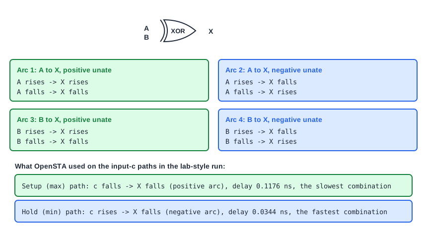
STA does not know the value of B, so it has to assume the worst case for every check. For each transition at the input, it evaluates every arc that can apply and keeps the largest delay for a setup check and the smallest for a hold check. Other libraries describe the same cell with state-dependent arcs, each with a when condition on the other input. The sky130 XOR does not use conditions, so both arcs always apply.
The lab-style run shows both arcs in use. On the path from input c to the data pin of r2, the setup (max) report uses the positive arc with a falling edge:
   0.0042    0.0000    0.0000    0.4000 v c (in)
             0.0000    0.0000    0.4000 v _4_/B (sky130_fd_sc_hd__xor2_1)
   0.0017    0.0367    0.1176    0.5176 v _4_/X (sky130_fd_sc_hd__xor2_1)
and the hold (min) report uses the negative arc with a rising input and a falling output:
   0.0045    0.0000    0.0000    0.4000 ^ c (in)
             0.0000    0.0000    0.4000 ^ _4_/B (sky130_fd_sc_hd__xor2_1)
   0.0017    0.0321    0.0344    0.4344 v _4_/X (sky130_fd_sc_hd__xor2_1)
The fastest way through the XOR (0.0344 ns) is a rising input turning into a falling output. The slowest (0.1176 ns) is a falling input turning into a falling output. Both belong to the same cell.
Common Mistakes
Mistake #1: Expecting one arc per input and output pair
A gate with a non-unate function, such as an XOR, has two arcs per input in this library. A path report shows only the arc STA picked for that check, so the other one is easy to overlook.
Mistake #2: Reading timing_sense as the function of the cell
The sense describes only how the direction of an edge maps from input to output. A positive unate arc does not mean the cell is non-inverting in every state of the other inputs, and a non-unate arc does not mean the output is unpredictable.
Quick Check: Which timing_type describes the delay from the clock pin to the Q pin of a flip-flop?
rising_edge for a flip-flop that triggers on the rising clock edge. Its sense is non_unate, because Q can rise or fall on the same clock edge, depending on the data.
Practice Exercise
Challenge: Find the XOR Arcs in a Report
Run the sta_demo design with the constraints from the first chapter (2.0 ns period, 0.4 ns input and output delays). In the setup report, find the path from c to the data pin of _6_, and in the hold report the path from c to the same pin. Write down the transition (^ or v) at c and at the XOR output for each. Then replace the input delay line with separate rise and fall delays and run again:
set_input_delay 0.4 -rise -clock clk [get_ports {a b c d}]
set_input_delay 0.1 -fall -clock clk [get_ports {a b c d}]
Predict which edge becomes critical for the setup path from c.
Open the ready-made example in the lab, run synthesis, and then run STA. Editing constraints.sdc and re-running only STA, and choosing another library or corner, are PRO features.
Hint
For each input edge, STA adds the input delay of that edge to the delay of the slowest XOR arc for that edge. The rising edge now starts at 0.4 ns and the falling edge at 0.1 ns.
Solution
In the first run the setup path is v c to v _4_/X (positive arc, 0.1176 ns) and the hold path is ^ c to v _4_/X (negative arc, 0.0344 ns). With the new input delays, the rising edge starts late, so the setup path becomes ^ c to ^ _4_/X, using the positive arc for a rising edge. Its XOR delay is 0.1079 ns, the data arrival time is 0.5079 ns, and the slack at _6_/D improves from 1.3650 to 1.4205 ns.
Summary
- Every arc is a
timing ()group inside the output pin, identified byrelated_pin,timing_senseandtiming_type. - The
timing_typeseparates delays (combinational, rising_edge) from checks (setup, hold, min_pulse_width, recovery, removal). - The timing sense says how edge directions map from input to output.
- A non-unate cell such as XOR is described with a positive and a negative arc from each input.
- For a setup check STA keeps the largest delay among the applicable arcs, and for a hold check the smallest.
