
The hold check protects data that a flip-flop is in the middle of capturing. It is easy to forget, because a design that fails hold looks fine on paper, and slowing the clock does not help. This article builds the hold equation step by step, shows why the clock period is not in it, and checks it on a real path with clock skew.
8 min read | Intermediate
What You'll Learn
- Explain which clock edges the hold check uses, and why they are the same edge
- Write the hold equation and calculate hold slack by hand
- Say why a hold violation does not depend on the clock frequency
- Predict how skew and clock uncertainty change the hold slack
The Question Hold Asks
A flip-flop needs its data input to stay still for a short time after the clock edge. That time is the hold time of the flip-flop, a number from the cell library. While the flip-flop is capturing, the old data must still be at the D pin.
Now think about two flip-flops in a row. At a clock edge, the second flip-flop captures the data at its D pin. At the very same edge, the first flip-flop sends out new data. If that new data runs through the logic very fast and reaches the second flip-flop before it has finished capturing, the old data is destroyed. The hold check makes sure the new data is slow enough. It asks: does the new data arrive late enough?
Which Edges
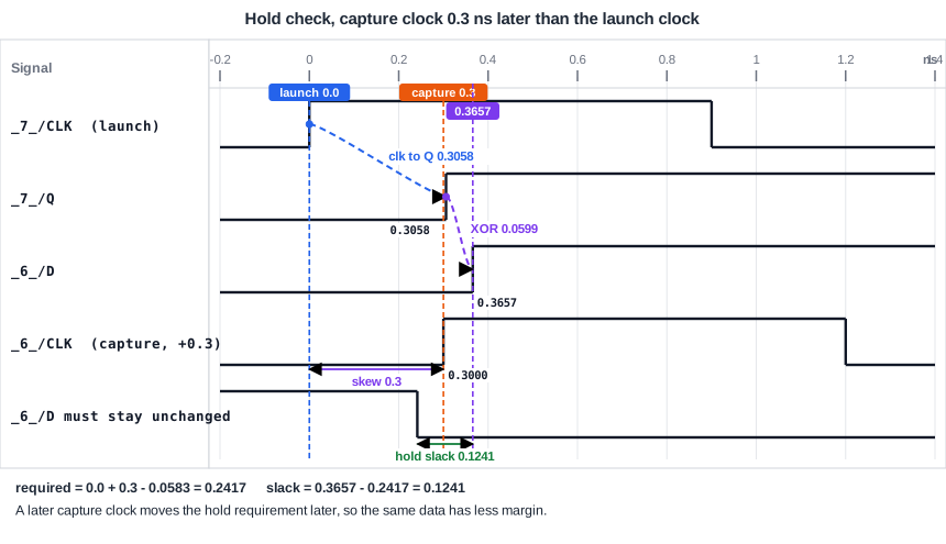
For setup, the data launched at one edge is captured at the next edge. For hold, the data launched at an edge must not disturb the capture that happens at the same edge. So both flip-flops use the same clock edge, the launch edge. Look at the diagram. The capture clock is 0.3 ns later than the launch clock, so the capture edge in question is the first edge on the capture clock, at 0.3 ns.
Step 1: The Data Arrival Time
For hold, the worst case is the data that is fastest, so STA uses the minimum delays. The data starts at the clock arrival time of the launch flip-flop, Tlaunch, and adds the smallest clock-to-Q delay and the smallest logic delay:
Data arrival time = Tlaunch + Tclk-to-Q(min) + Tdp(min)
The smallest value is not found by simply taking the shortest-looking path. Rising and falling edges have different delays, and STA picks the combination that gives the smallest total. In our path, a rising output of the flip-flop (0.3058 ns) followed by a falling output of the XOR gate (0.0599 ns) is the fastest combination. The total is 0.3657 ns. In the setup check, the slowest combination was a falling output of the flip-flop (0.2874 ns) and a falling XOR (0.1450 ns), which gave 0.4323 ns.
Step 2: The Data Required Time
The data must not change before the capture flip-flop has finished with the old value. The capture flip-flop needs the old value for the hold time after the capture edge, so the earliest allowed arrival is:
Data required time = Tcapture + Thold
This time is the capture clock arrival time Tcapture plus the hold time. In the library, the hold time of our flip-flop is -0.0583 ns, and it is negative. A negative hold time means the flip-flop does not need the old data after the edge at all; it needs it to stay until slightly before the edge. That makes the check easier to meet.
Step 3: Compare
The data must arrive at or after the required time. The hold slack is arrival minus required, the opposite order from setup, so that a positive number always means the check is met:
Hold check:  Tlaunch + Tclk-to-Q(min) + Tdp(min)  >=  Tcapture + Thold

Hold slack = (Tlaunch + Tclk-to-Q(min) + Tdp(min)) - (Tcapture + Thold)
A Real Example
With the capture clock 0.3 ns late, as in the setup article, the numbers are:
| Term | Value (ns) |
|---|---|
| Data arrival time = 0 + 0.3058 + 0.0599 | 0.3657 |
| Data required time = 0.3 + (-0.0583) | 0.2417 |
| Hold slack = 0.3657 - 0.2417 | 0.1241 |
The report agrees:
   0.0000    0.0000   clock clk (rise edge)
   0.3000    0.3000   clock network delay (ideal)
   0.0000    0.3000   clock reconvergence pessimism
             0.3000 ^ _6_/CLK (sky130_fd_sc_hd__dfxtp_1)
  -0.0583    0.2417   library hold time
             0.2417   data required time
            -0.3657   data arrival time
             0.1241   slack (MET)
Without the skew, the hold slack was 0.4241 ns. A late capture clock moved the required time later by 0.3 ns, and the hold slack went down by exactly 0.3 ns. This is the opposite of setup: a late capture clock helps setup and hurts hold.
Why the Clock Period Is Not in the Equation
Compare the hold equation with the setup equation. The period Tperiod is missing. The reason is that both flip-flops use the same clock edge, so no full clock cycle lies between them. The hold check is a race between the new data and the clock edge, and the length of the clock cycle does not matter.
You can see it in the tool. Set the period to 10.0 ns instead of 2.0 ns and run again. The setup slack grows from 1.7502 to 9.7502 ns, but the hold slack is still 0.1241 ns. This has an important consequence: a hold violation cannot be repaired by running the chip slower. A chip with a hold violation can fail at every frequency, including at a very low one.
Adding Margin: Clock Uncertainty
For hold, clock uncertainty is added to the required time, which makes the check harder:
Data required time = Tcapture + Thold + Tuncertainty
With a hold uncertainty of 0.1 ns and no skew, the required time of our path is 0.0 + (-0.0583) + 0.1 = 0.0417 ns and the hold slack is 0.3657 - 0.0417 = 0.3241 ns.
Common Mistakes
Mistake #1: Using the slowest delays for the hold check
Hold looks for the data that arrives earliest, so it uses the smallest delays. Taking the delays of the setup check gives a hold slack that is too good, and a violation is missed.
Mistake #2: Trying to fix a hold violation with a slower clock
The clock period does not appear in the hold equation. Slowing the clock changes the setup slack and leaves the hold slack where it was.
Quick Check: The earliest data arrival is 0.25 ns, the capture clock arrives at 0.10 ns and the hold time is 0.05 ns. What is the hold slack?
Required time = 0.10 + 0.05 = 0.15 ns. Slack = 0.25 - 0.15 = 0.10 ns, so the check is met.
Practice Exercise
Challenge: Break the Hold Check With Skew
Use the sta_demo design at a 2.0 ns period. Delay the clock of the capturing flip-flop (_6_ in our run) by 0.5 ns, and run STA:
set_clock_latency 0.5 [get_pins _6_/CLK]
Predict the hold slack of the path from _7_ to _6_ and say whether the check is met. Then predict what the setup slack does.
Open the ready-made example in the lab, run synthesis, and then run STA. Editing constraints.sdc and re-running only STA, and choosing another library or corner, are PRO features.
Hint
The data arrival time is still 0.3657 ns, because the launch clock did not change. Find the new required time first.
Solution
The required time is 0.5 + (-0.0583) = 0.4417 ns, and the data arrives at 0.3657 ns, so the hold slack is 0.3657 - 0.4417 = -0.0759 ns. The check is violated. The setup slack becomes 2.3826 - 0.4323 = 1.9502 ns, which is better than before. One change to the clock helped one check and broke the other. Setting the period to 10 ns would not remove the hold violation.
Summary
- The hold check makes sure that new data does not reach a flip-flop while it is still capturing the old data.
- Hold uses the same clock edge at the launch and the capture flip-flop, and the smallest delays.
- Data arrival time = launch clock arrival + minimum clock-to-Q delay + minimum logic delay.
- Data required time = capture clock arrival + hold time (plus clock uncertainty).
- Hold slack = arrival time - required time. Zero or more means met.
- The clock period is not in the equation, so slowing the clock never fixes a hold violation.
- A later capture clock lowers the hold slack, and a later launch clock raises it.
