
Setup and hold cover the data pin of a flip-flop. A chip has other places where timing matters: reset pins, latches, clock pulses and interfaces that use both clock edges. Each of them has its own check, and each is a variation of the same two ideas, a signal that must be there in time and a signal that must not change too soon. This chapter covers those special checks.
A flip-flop with an asynchronous reset has a reset pin that acts at any time, without waiting for the clock. When the reset is released, the flip-flop goes back to normal operation, and that release must not happen too close to a clock edge. The checks that guard this are called recovery and removal. This article explains them, shows a real report, and gives the values for a library flip-flop.
8 min read | Intermediate
What You'll Learn
- Explain what happens when an asynchronous reset is released close to a clock edge
- Describe the recovery and removal checks and compare them with setup and hold
- Read the recovery and removal paths in a timing report
- Say how the checks are constrained and where they appear in the reports
The Asynchronous Reset
This is a flip-flop with an active-low asynchronous reset:
module sta_rst (input clk, rst_n, d, output reg q);
  always @(posedge clk or negedge rst_n)
    if (!rst_n) q <= 1'b0; else q <= d;
endmodule
While rst_n is low, the output is forced to 0, whatever the clock does. When rst_n goes high again, the reset is released and the flip-flop follows its data on the next clock edge.
Why Release Matters
The danger is the moment of release. If the reset is released at the same time as a clock edge, the flip-flop does not know whether it should still be in reset or whether it should capture its data. It can end in an undefined state, the same instability that a setup violation causes on a data pin. The cure is the same as for data: keep the release away from the clock edge, on both sides. The two sides have two names:
- Recovery: the release must come early enough before the next clock edge, so that the flip-flop has time to recover from the reset. It is the counterpart of setup.
- Removal: the release must not come too soon after a clock edge, so that the reset stays active until the edge is done with it. It is the counterpart of hold.
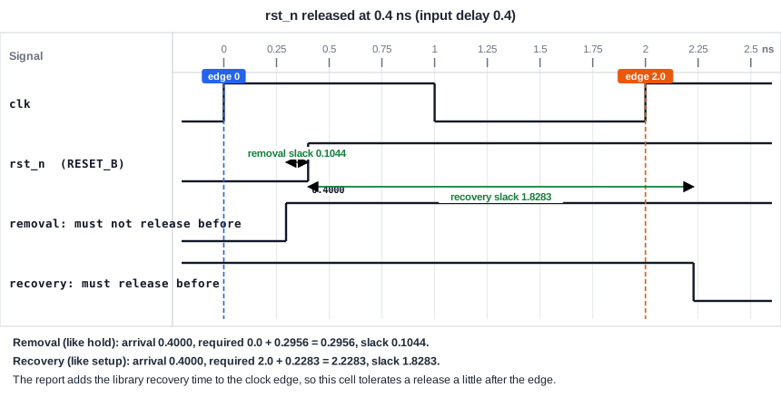
The Reports
STA finds the asynchronous pin of a flip-flop in the library and makes both checks automatically. They are in their own path group, asynchronous. The input rst_n has an input delay of 0.4 ns, as every input in this example. The recovery check, which is a setup-like check, uses the latest release time:
Startpoint: rst_n (input port clocked by clk)
Endpoint: _0_ (recovery check against rising-edge clock clk)
Path Group: asynchronous
Path Type: max

   0.4000    0.4000 ^ input external delay
   0.0000    0.4000 ^ rst_n (in)
   0.0000    0.4000 ^ _0_/RESET_B (sky130_fd_sc_hd__dfrtp_1)
             0.4000   data arrival time

   2.0000    2.0000   clock clk (rise edge)
   2.0000 ^ _0_/CLK (sky130_fd_sc_hd__dfrtp_1)
   0.2283    2.2283   library recovery time
             2.2283   data required time
             1.8283   slack (MET)
The endpoint is described as a recovery check against rising-edge clock clk. The reset arrives at 0.4 ns, the clock edge is at 2.0 ns, and the library value is added to the clock edge: in this library, the report adds 0.2283 ns to the edge, so the flip-flop accepts a release up to 0.2283 ns after the edge. The slack is 2.2283 - 0.4 = 1.8283 ns.
The removal check is a hold-like check, with the earliest release time:
Endpoint: _0_ (removal check against rising-edge clock clk)
Path Group: asynchronous
Path Type: min

   0.4000    0.4000 ^ input external delay
   0.4000 ^ _0_/RESET_B (sky130_fd_sc_hd__dfrtp_1)
             0.4000   data arrival time

   0.0000    0.0000   clock clk (rise edge)
   0.0000 ^ _0_/CLK (sky130_fd_sc_hd__dfrtp_1)
   0.2956    0.2956   library removal time
             0.2956   data required time
             0.1044   slack (MET)
The reset must not be released before 0.2956 ns after the clock edge at time 0. It arrives at 0.4 ns, so the slack is 0.4 - 0.2956 = 0.1044 ns, which is a small margin. The removal check is the one to watch in this example. As for the hold check, a large input delay is a help and a small one is a risk.
Constraining the Checks
You do not write anything special for these checks. The reset port needs an input delay, as any input, and the flip-flops need their clock. The delay of the reset path inside the chip, from the port or from the flip-flop that makes the reset to the reset pin, is part of the arrival time. If it comes from a flip-flop, STA uses the clock-to-Q delay and the wires, as in a data path. The checks use the same clock as data checks. After a reset synchronizer, the release is synchronous to the clock, and the recovery and removal checks are met as for normal data.
Where to Look in the Reports
Recovery and removal are listed in the path group asynchronous. If you only look at the group of the clock, you will not see them. In the summary, the pin appears as RESET_B and not as D:
max_delay/setup group asynchronous
_0_/RESET_B (sky130_fd_sc_hd__dfrtp_1)    2.2283    0.4000    1.8283 (MET)

min_delay/hold group asynchronous
_0_/RESET_B (sky130_fd_sc_hd__dfrtp_1)    0.2956    0.4000    0.1044 (MET)
Common Mistakes
Mistake #1: Leaving the reset port without an input delay
Without it the recovery and removal paths from the reset input are not checked, and check_setup lists the port. A reset that comes from outside needs a constraint like any other input.
Mistake #2: Looking only at the data pins
A design can meet all the setup and hold checks and still violate recovery or removal. Always read the asynchronous group.
Quick Check: Which of the two checks, recovery or removal, is like a hold check?
Removal. It asks that the reset is not released too soon after the clock edge, and it uses the earliest release time, as a hold check does.
Practice Exercise
Challenge: Move the Reset Release
Paste the sta_rst design into the lab with a 2.0 ns clock and an input delay of 0.4 ns on rst_n and d. Look at the removal slack in the asynchronous group. Then change the input delay of the reset to 0.2 ns:
set_input_delay 0.2 -clock clk [get_ports rst_n]
Predict the removal slack and the recovery slack.
Open the ready-made example in the lab, run synthesis, and then run STA. Editing constraints.sdc and re-running only STA, and choosing another library or corner, are PRO features.
Hint
The arrival time of the reset release changes by the same amount as the input delay. The required times stay the same.
Solution
The arrival time is now 0.2 ns, so the removal slack is 0.2 - 0.2956 = -0.0956 ns, which is a violation: the reset is released too soon after the clock edge. The recovery slack becomes 2.2283 - 0.2 = 2.0283 ns. A smaller delay helps recovery and hurts removal, as for setup and hold.
Summary
- The release of an asynchronous reset must keep a distance from the clock edge, or the flip-flop can become unstable.
- Recovery is the setup-like check before the next edge, and removal is the hold-like check after the edge.
- STA adds both checks automatically for every flip-flop with an asynchronous pin, in the path group
asynchronous. - The reset input needs an input delay, or the checks are missing.
- A smaller delay on the release helps recovery and hurts removal.
