
Verilog needs to represent individual bits as well as groups of bits. For example, a single bit sequential element is a flip-flop. However a 16-bit sequential element is a register that can hold 16 bits. For this purpose, Verilog has scalar and vector nets and variables.
What You'll Learn
- The difference between scalar and vector nets and variables
- How to select a single bit of a vector
- How constant and indexed part-selects pick a range of bits
- Common range and select mistakes, and how to avoid them
Scalar and Vector
A net or reg declaration without a range specification is considered 1-bit wide and is a scalar. If a range is specified, then the net or reg becomes a multibit entity known as a vector.
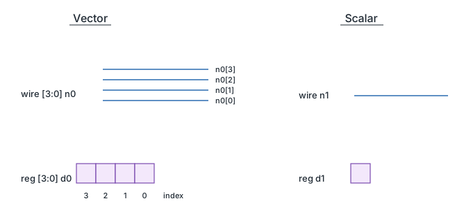
	wire 	 o_nor; // single bit scalar net
	wire [7:0] o_flop; // 8-bit vector net
	reg parity; // single bit scalar variable
	reg [31:0] addr; // 32 bit vector variable to store address
The code examples shown above are synthesizable and can be implemented in hardware. Always simulate your design before synthesis to verify correct functionality.
The range gives the ability to address individual bits in a vector. The most significant bit of the vector should be specified as the left hand value in the range while the least significant bit of the vector should be specified on the right.
	wire [msb:lsb] name;
	integer my_msb;

	wire [15:0] priority; // msb = 15, lsb = 0
	wire [my_msb: 2] prior; // illegal
A 16 bit wide net called priority will be created in the example above. Note that the msb and lsb should be a constant expression and cannot be substituted by a variable. But they can be any integer value - positive, negative or zero; and the lsb value can be greater than, equal to or less than msb value.
Bit-selects
Any bit in a vectored variable can be individually selected and assigned a new value as shown below. This is called as a bit-select. If the bit-select is out of bounds or the bit-select is x or z, then the value returned will be x.

	reg [7:0] addr; // 8-bit reg variable [7, 6, 5, 4, 3, 2, 1, 0]

	addr [0] = 1; // assign 1 to bit 0 of addr
	addr [3] = 0; // assign 0 to bit 3 of addr
	addr [8] = 1; // illegal : bit8 does not exist in addr
Part-selects
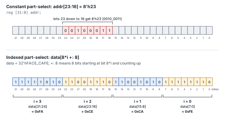
A range of contiguous bits can be selected and is known as a part-select. There are two types of part-selects, one with a constant part-select and another with an indexed part-select.
Industry Application
This technique is employed in high-performance computing systems, where efficient hardware implementation is critical. Synthesis tools optimize this construct into area-efficient gate-level logic.
	reg [31:0] addr;

	addr [23:16] = 8'h23; // bits 23 to 16 will be replaced by the new value 'h23 -> constant part-select
Having a variable part-select allows it to be used effectively in loops to select parts of the vector. Although the starting bit can be varied, the width has to be constant.
[<start_bit> +: <width>] // part-select increments from start-bit
[<start_bit> -: <width>] // part-select decrements from start-bit
module des;
  reg [31:0] data;
  integer i;

  initial begin
    data = 32'hFACE_CAFE;
    for (i = 0; i < 4; i = i+1) begin
      $display ("data[8*%0d +: 8] = 0x%0h", i, data[8*i +: 8]);
    end

    $display ("data[7:0] = 0x%0h", data[7:0]);
    $display ("data[15:8] = 0x%0h", data[15:8]);
    $display ("data[23:16] = 0x%0h", data[23:16]);
    $display ("data[31:24] = 0x%0h", data[31:24]);
  end

endmodule
ncsim> run
data[8*0 +: 8] = 0xfe // ~ data [8*0+8 : 8*0]
data[8*1 +: 8] = 0xca // ~ data [8*1+8 : 8*1]
data[8*2 +: 8] = 0xce // ~ data [8*2+8 : 8*2]
data[8*3 +: 8] = 0xfa // ~ data [8*3+8 : 8*3]

data[7:0] = 0xfe
data[15:8] = 0xca
data[23:16] = 0xce
data[31:24] = 0xfa
ncsim: *W,RNQUIE: Simulation is complete.
Common Errors
module tb;
 reg [15:0] data;

 initial begin
 $display ("data[0:9] = 0x%0h", data[0:9]); // Error : Reversed part-select index expression ordering
 end
endmodule
Common Beginner Mistakes
Mistake #1: Bit-Width Mismatches in Assignments
Assigning a 4-bit vector to a 2-bit wire (or vice versa) is a silent killer. Verilog will often truncate the most significant bits or zero-extend the signal without throwing a hard error, leading to logic that "mostly" works but fails on specific values.
Best Practice: Always ensure the bit-width of the source and destination match exactly: wire [3:0] bus_a = bus_b[3:0];
Mistake #2: Confusing Little-Endian and Big-Endian Indexing
Mixing [7:0] (Little-Endian) and [0:7] (Big-Endian) definitions in the same design is a recipe for disaster. If you define a bus as [0:7] but access it as bus[0], you may be grabbing the most significant bit instead of the least significant bit, effectively flipping your data.
Best Practice: Stick to the Verilog industry standard of [MSB:LSB] (e.g., [7:0]) for all declarations vs [0:7] bit order].
Mistake #3: Multi-Driven Nets (Short Circuits)
In software, you can overwrite a variable. In Verilog, a wire represents a physical connection. If you use two different assign statements for the same scalar or vector, you are physically soldering two outputs together. This results in an X (unknown) state in simulation.
Best Practice: Ensure each wire or reg is driven by only one continuous assignment or one procedural block.
Mistake #4: Forgetting the Range in Port Connections
When connecting a vector to a module port, beginners often forget to specify the range or accidentally pass a single bit when the module expects the whole bus. Writing my_module inst(.data_in(bus)) is fine, but (.data_in(bus[0])) only sends one wire to a multi-pin input.
Best Practice: Use the Concatenation Operator { } to combine scalars into vectors or to join smaller vectors into a larger bus. For example, {4'b1010, 4'b0000} creates a single 8-bit vector 8'b10100000.
Practice Exercise
Challenge: Select Bits and Bytes
A 32-bit variable holds 32'h1234_ABCD. Display bit 0, bits [7:0], bits [31:24], and the byte at bits [23:16] using an indexed part-select.
Hint
A single bit uses data[0]. For the third byte, data[16 +: 8] starts at bit 16 and takes 8 bits upward.
Solution
module tb;
  reg [31:0] data;

  initial begin
    data = 32'h1234_ABCD;
    $display("data[0]       = %b",    data[0]);
    $display("data[7:0]     = 0x%0h", data[7:0]);
    $display("data[31:24]   = 0x%0h", data[31:24]);
    $display("data[16 +: 8] = 0x%0h", data[16 +: 8]);
  end
endmodule
The output is 1, 0xcd, 0x12 and 0x34. The last line is the same as data[23:16], but the start bit can be a variable, which is useful inside loops.
Summary
In this tutorial, you learned:
- A net or
regwithout a range is a 1-bit scalar; with a range[msb:lsb]it is a vector - The range bounds must be constant expressions, and the left bound is the most significant bit by convention
- A bit-select picks one bit, and a part-select picks a contiguous range of bits
[start +: width]and[start -: width]allow a variable start with a constant width- A bit-select that is out of range, or that uses x or z as the index, returns x
- A part-select must use the same bit order as the declaration
