
An always block is one of the procedural blocks in Verilog. Statements inside an always block are executed sequentially.
What You'll Learn
- Master sensitivity lists and event-driven execution for combinational and sequential logic
- Understand the critical difference between level-sensitive and edge-sensitive always blocks
- Apply synthesis templates to avoid latches and ensure proper hardware inference
- Recognize when to use blocking (
=) vs nonblocking (<=) assignments in always blocks
Syntax
always @ (event)
	[statement]

always @ (event) begin
	[multiple statements]
end
The always block is executed at some particular event. The event is defined by a sensitivity list.
What is the sensitivity list ?
A sensitivity list is the expression that defines when the always block should be executed and is specified after the @ operator within parentheses ( ). This list may contain either one or a group of signals whose value change will execute the always block.
In the code shown below, all statements inside the always block get executed whenever the value of signals a or b change.
// Level-sensitive: Execute always block whenever value of "a" or "b" change
// This is used for combinational logic
always @ (a or b) begin
	[statements]
end
What is the always block used for ?
An always block can be used to realize combinational or sequential elements. A sequential element like flip flop becomes active when it is provided with a clock and reset. Similarly, a combinational block becomes active when one of its input values change. These hardware blocks are all working concurrently independent of each other. The connection between each is what determines the flow of data. To model this behavior, an always block is made as a continuous process that gets triggered and performs some action when a signal within the sensitivity list becomes active.
In the following example, all statements within the always block get executed at every positive edge of the signal clk.
// Edge-sensitive: Execute always block at positive edge of signal "clk"
// This is used for sequential logic (flip-flops, registers)
always @ (posedge clk) begin
	[statements]
end
What happens if there is no sensitivity list ?
The always block repeats continuously throughout the duration of a simulation. The sensitivity list brings along a certain sense of timing i.e. whenever any signal in the sensitivity list changes, the always block is triggered. If there are no timing control statments within an always block, the simulation will hang because of a zero-delay infinite loop !
Example
The example shown below is an always block that attempts to invert the value of the signal clk. The statement is executed after every 0 time units. Hence, it executes forever because of the absence of a delay in the statement.
// WRONG: No sensitivity list and no delay - simulation hangs!
// always block is started at time 0 units
// But when is it supposed to be repeated?
// There is no time control, and hence it will stay and
// be repeated at 0 time units only. This continues
// in a loop and simulation will hang!
always clk = ~clk;
Even if the sensitivity list is empty, there should be some other form of time delay. Simulation time is advanced by a delay statement within the always construct as shown below. Now, the clock inversion is done after every 10 time units.
	// CORRECT for testbenches: Explicit delay creates clock with 20ns period
	// Toggles every 10ns: high for 10ns, low for 10ns
	always #10 clk = ~clk;
Note: Explicit delays are not synthesizable into logic gates !
Hence real Verilog design code always require a sensitivity list.
Sequential Element Design Example
The code shown below defines a module called tff that accepts a data input, clock and active-low reset. The output gets inverted whenever d is found to be 1 at the positive edge of clock. Here, the always block is triggered either at the positive edge of clk or the negative edge of rstn.
What happens at the positive edge of clock ?
The following events happen at the positive edge of clock and is repeated for all positive edge of clock.
- First
ifblock checks value of active-low reset rstn - If rstn is zero, then output q should be reset to default value of 0
- If rstn is one, then it means reset is not applied and should follow default behavior
- If the previous step is false:
- Check value of d and if it is found to be one, then invert value of q
- If d is 0, then maintain value of q
module tff (input 		d,       // Data input: toggles output when high
						clk,     // Clock signal: triggers on rising edge
						rstn,    // Active-low asynchronous reset
			output reg 	q);       // Output register (must be reg in always block)

	// Edge-sensitive always block: Triggered on posedge clk OR negedge rstn
	// This implements asynchronous reset behavior
	always @ (posedge clk or negedge rstn) begin
		if (!rstn)
			q <= 0;    // Asynchronous reset: Immediately set q to 0
		else
			// Synchronous behavior: Only evaluated at clock edges
			if (d)
				q <= ~q;   // Toggle output when d=1
			else
				q <= q;    // Hold output when d=0
	end
endmodule
What happens at the negative edge of reset ?
The following events happen at negative edge of rstn and happen at all such occurrences.
- First
ifblock checks value of active-low reset rstn. At negative edge of the signal, its value is 0. - If value of rstn is 0, then it means reset is applied and output should be reset to default value of 0
- The case where value of rstn is 1 is not considered because the current event is negative edge of the rstn
Combinational Element Design Example
An always block can also be used in the design of combinational blocks. For example the following digital circuit represents a combination of three different logic gates that provide a certain output at signal o.
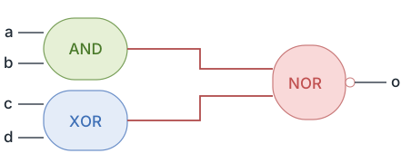
The code shown below is a module with four input ports and a single output port called o. The always block is triggered whenever any of the signals in the sensitivity list changes in value. Output signal is declared as type reg in the module port list because it is used in a procedural block. All signals that are assigned inside a procedural block should be declared as type reg.
module combo (	input 	a,
 			          input	  b,
                input	  c,
                input	  d,
 	              output reg o);  // Output must be 'reg' type for procedural assignment

  // Level-sensitive always block: Triggers when ANY input changes
  // This infers combinational logic (no clock, no memory elements)
  always @ (a or b or c or d) begin
    // Combinational expression: o = NOT((a AND b) OR (c XOR d))
 	  o = ~((a & b) | (c^d));
  end

endmodule
See that the signal o becomes 1 whenever the combinational expression on the RHS becomes true. Similarly o becomes 0 when RHS is false.
Simulation Output
Synthesis
It is possible for an always block to not be synthesis friendly, if it does not follow one of the following templates.
// ========== SYNTHESIS TEMPLATE #1: COMBINATIONAL LOGIC ==========
// Use for: Pure combinational logic (no memory, no state)
// Key requirement: ALL inputs in sensitivity list (or use always @(*) in Verilog-2001)
// Result: Infers gates (AND, OR, NOT, MUX, etc.)
always @ (all_inputs) begin
	// Combinational logic - no if without else (causes latch!)
	// Use blocking (=) for combo, but nonblocking (<=) also works
end

// ========== SYNTHESIS TEMPLATE #2: LATCH (USUALLY UNINTENDED!) ==========
// CAUTION: if without else creates a latch to hold previous value
// Latches are usually unintended bugs in digital design
// Missing else clause -> output not defined for all cases -> infers memory
always @ (all_inputs) begin
	if (enable) begin
		// latch value assignments
	end
	// MISSING else -> Latch inferred! Previous value held when enable=0
end

// ========== SYNTHESIS TEMPLATE #3: SYNCHRONOUS SEQUENTIAL LOGIC ==========
// Use for: Flip-flops, registers, counters (synchronous reset)
// Key requirement: Only clock in sensitivity list
// Result: Infers D flip-flops
always @ (posedge clk) begin
	// Sequential logic with synchronous reset
	// Always use nonblocking (<=) assignments
	if (sync_reset) begin
		// reset behavior (happens at clock edge)
	end else begin
		// normal behavior
	end
end

// ========== SYNTHESIS TEMPLATE #4: ASYNC RESET SEQUENTIAL LOGIC ==========
// Use for: Flip-flops with asynchronous reset (most common in ASIC/FPGA)
// Key requirement: Clock edge AND reset edge in sensitivity list
// Result: Infers D flip-flops with async reset/set
always @ (posedge clk or negedge resetn) begin
	if (! resetn) begin
		// Async reset behavior: Executes immediately on resetn falling edge
		// Independent of clock - resets happen instantly
	end else begin
		// Synchronous behavior: Only executes on clock rising edge
	end
end
| Sensitivity List Type | Example | Hardware Inferred | Use Case |
|---|---|---|---|
| Level-sensitive (all inputs) | always @(a or b or c) | Combinational logic (gates) | ALUs, decoders, multiplexers |
| Edge-sensitive (clock only) | always @(posedge clk) | D flip-flops (sync reset) | Registers, counters, state machines |
| Edge-sensitive (clock + async reset) | always @(posedge clk or negedge rst) | D flip-flops (async reset) | Most ASIC/FPGA sequential designs |
| Level-sensitive (incomplete) | always @(enable) if (enable) q=d; | Latch (usually unintended!) | Rarely intentional - often a bug |
Real-World Application: Microprocessor Register File
In CPU designs, register files use edge-sensitive always blocks with asynchronous resets. Each register uses always @(posedge clk or negedge rst_n) to ensure data is captured exactly on clock rising edges, while reset can immediately clear all registers independent of the clock. This is critical for power-on initialization and debug scenarios where the system needs instant reset without waiting for a clock edge. Modern ARM Cortex-M processors use this pattern for their 32 general-purpose registers (R0-R15).
Real-World Application: FPGA Clock Domain Crossing
When signals cross between different clock domains in FPGAs, synchronizer chains use multiple always blocks with different clock sensitivity lists. A typical two-flop synchronizer has one always block sensitive to posedge clk_src and another sensitive to posedge clk_dest. Each block uses nonblocking assignments (<=) to prevent race conditions. This pattern is essential in FPGA designs handling multiple clocks (e.g., PCIe at 125MHz, DDR at 400MHz, user logic at 100MHz).
Common Beginner Mistakes
Mistake #1: Incomplete Sensitivity List Causing Simulation-Synthesis Mismatch
// WRONG: Missing 'c' in sensitivity list
always @(a or b) begin
  out = (a & b) | c;  // 'c' not in sensitivity list
end

// Simulation: Block only triggers when a or b changes, NOT when c changes
// Synthesis: Tools infer combinational logic considering ALL inputs (a, b, c)
// Result: Simulation doesn't match hardware!
Why it's problematic: Incomplete sensitivity lists cause simulation to behave differently than synthesized hardware. Simulation only triggers on listed signals, while synthesis tools analyze the code and create hardware responding to all inputs. This creates a dangerous mismatch where your testbench passes in simulation but the silicon fails.
Best Practice: For combinational logic, use always @(*) (Verilog-2001) or always_comb (SystemVerilog) which automatically include all inputs. For sequential logic, only list clock and async control signals. See our guide on Combinational Logic.
Mistake #2: Using Blocking Assignments in Sequential Logic
// WRONG: Blocking assignments in clocked always block
always @(posedge clk) begin
  temp = a + b;      // Blocking (=) - executes immediately
  result = temp * 2; // Uses NEW value of temp
end

// Creates combinational path: result = (a + b) * 2 in ONE clock cycle
// Expected: Pipelined behavior with temp registered first
Why it's problematic: Blocking assignments (=) execute sequentially in zero time, creating unintended combinational logic within sequential blocks. This defeats pipelining, causes timing violations, and creates race conditions when multiple always blocks interact. The code looks like a 2-stage pipeline but synthesizes as combinational logic with long critical paths.
Best Practice: Always use nonblocking assignments (<=) in clocked always blocks. This ensures variables update simultaneously at clock edges, matching real flip-flop behavior. Blocking assignments are for combinational always blocks only. See our tutorial on Blocking vs Nonblocking.
Mistake #3: Mixing Combinational and Sequential Logic in Same Always Block
// WRONG: Mixing combo and sequential logic
always @(posedge clk or a or b) begin  // Clock edge AND level-sensitive!
  if (reset)
    q <= 0;
  else
    q <= a + b;  // Is this registered or combinational?
end

// Synthesis tools reject this - sensitivity list is ambiguous
Why it's problematic: Sensitivity lists combining edge-sensitive (posedge clk) and level-sensitive (a or b) signals are nonsensical and rejected by synthesis tools. The block can't be both combinational (responds to input changes) and sequential (triggered by clock edges) simultaneously. This confuses the inference engine, resulting in synthesis errors or warnings.
Best Practice: Use separate always blocks for combinational and sequential logic. Combinational: always @(*) with blocking =. Sequential: always @(posedge clk) with nonblocking <=. Never mix edge and level sensitivity in one block.
Mistake #4: Forgetting to Declare Outputs as 'reg' in Always Blocks
module counter (
  input clk,
  output [7:0] count  // WRONG: Should be 'output reg'
);

always @(posedge clk) begin
  count <= count + 1;  // ERROR: Cannot assign to wire 'count'
end
endmodule
Why it's problematic: Outputs driven by procedural blocks (always, initial, task, function) must be declared as reg type. The keyword reg doesn't mean hardware register - it just indicates the signal is assigned procedurally rather than continuously. Forgetting this causes compilation errors: "cannot assign to wire" or "left-hand side of assignment must be a variable."
Best Practice: Declare outputs as output reg when driven from always blocks: output reg [7:0] count. For continuous assignments (assign), use plain output wire. SystemVerilog simplifies this with logic type that works for both. See our guide on Ports.
Summary
In this tutorial, you learned:
alwaysblocks are procedural constructs executing sequentially, triggered by sensitivity lists defining level-sensitive (combinational) or edge-sensitive (sequential) behavior- Level-sensitive always blocks (
@(a or b)) infer combinational logic; edge-sensitive blocks (@(posedge clk)) infer flip-flops for sequential logic - Complete sensitivity lists are critical - missing inputs cause simulation-synthesis mismatches; use
@(*)for automatic inference in combinational blocks - Four synthesis templates exist: combinational (all inputs), latch (incomplete outputs), synchronous sequential (clock only), async sequential (clock + reset edge)
- Outputs driven from always blocks must be declared
regtype; use nonblocking (<=) for sequential, blocking (=) for combinational logic
