
A 4 to 1 multiplexer (mux) in Verilog routes one of four data inputs to a single output based on a 2-bit select signal. You can write it with an assign statement, a case statement, an if-else-if chain, or an indexed part-select, and every form synthesizes into the same selection hardware.
10 min read | Beginner Level
What You'll Learn
- How a 4 to 1 mux selects data and what its Boolean equation looks like
- Four ways to write a 4x1 mux in Verilog and when to use each
- What each coding style becomes after synthesis
- How to verify the mux with a testbench and avoid latch and select-width bugs
What is a mux or multiplexer?
A multiplexer, or mux, is a combinational circuit that passes one of N inputs to its output. A 4 to 1 mux has four data inputs, so it needs a 2-bit select signal (sel) to pick between them, since 22 = 4.
Each input can be more than one bit wide. A 4-bit, 4 to 1 mux has four 4-bit inputs (a, b, c, d) and one 4-bit output (out). Internally this is four identical 1-bit muxes that share the same sel lines.
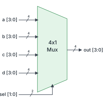
The table below shows which input reaches out for each value of sel, using example values a = 3, b = 7, c = 1 and d = 9.
| sel | a | b | c | d | out |
|---|---|---|---|---|---|
| 2'b00 | 3 | 7 | 1 | 9 | 3 (a) |
| 2'b01 | 3 | 7 | 1 | 9 | 7 (b) |
| 2'b10 | 3 | 7 | 1 | 9 | 1 (c) |
| 2'b11 | 3 | 7 | 1 | 9 | 9 (d) |
For each output bit, the mux implements this sum-of-products equation:
out = (~sel[1] & ~sel[0] & a) |
      (~sel[1] &  sel[0] & b) |
      ( sel[1] & ~sel[0] & c) |
      ( sel[1] &  sel[0] & d)
Each product term is one decoded value of sel. Only one term can be true at a time, so the OR gate never combines two inputs. This mutual exclusivity is what separates a mux from priority logic.
Syntax: Quick Reference
A mux has no dedicated Verilog keyword. You describe the selection behavior with one of these constructs and the synthesis tool recognizes the pattern.
Basic Forms:
// 1. Continuous assignment with nested conditional (ternary) operator
assign out = sel[1] ? (sel[0] ? d : c) : (sel[0] ? b : a);

// 2. case statement inside a combinational always block
always @(*) begin
  case (sel)
    2'b00 : out = a;
    2'b01 : out = b;
    2'b10 : out = c;
    2'b11 : out = d;
  endcase
end

// 3. Indexed part-select on a packed input bus
assign out = in_bus[sel*4 +: 4];
Components:
sel- Select input,$clog2(N)bits wide for N inputs (required)a, b, c, d- Data inputs, all the same width asout(required)out- Declared aswireforassign, and asregwhen driven from analwaysblock
Using assign statement
The conditional operator ? : is a 2 to 1 mux in a single expression. Nesting three of them builds a 4 to 1 mux: sel[1] picks between the lower pair (a, b) and the upper pair (c, d), and sel[0] picks within each pair. See Verilog assign statement for how continuous assignments work.
module mux_4to1_assign (
  input  [3:0] a,     // Data input, selected when sel = 2'b00
  input  [3:0] b,     // Data input, selected when sel = 2'b01
  input  [3:0] c,     // Data input, selected when sel = 2'b10
  input  [3:0] d,     // Data input, selected when sel = 2'b11
  input  [1:0] sel,   // 2-bit select: 4 combinations for 4 inputs
  output [3:0] out    // Selected data; a wire because assign drives it
);

  // Outer ternary: sel[1] chooses the upper pair (c/d) or the lower pair (a/b)
  // Inner ternaries: sel[0] chooses one input within the chosen pair
  assign out = sel[1] ? (sel[0] ? d : c)
                      : (sel[0] ? b : a);

endmodule
Synthesis result: The nested ternary maps directly onto a two-level tree of 2 to 1 muxes. Level one has two muxes controlled by sel[0]; level two has one mux controlled by sel[1]. Synthesis tools usually merge this tree into a single 4 to 1 mux cell when the library has one.
Running this design with the testbench shown later produces the following output:
$ /usr/bin/vvp simulation +random_seed+1291169153
[0] sel=0x0 a=0x4 b=0x1 c=0x9 d=0x3 out=0x4
[5] sel=0x1 a=0x4 b=0x1 c=0x9 d=0x3 out=0x1
[10] sel=0x2 a=0x4 b=0x1 c=0x9 d=0x3 out=0x9
[15] sel=0x3 a=0x4 b=0x1 c=0x9 d=0x3 out=0x3
testbench.v:41: $finish called at 20 (1ns)
Where is a 4 to 1 Mux Used?
Processor datapaths use muxes to pick an ALU operand from several sources: a register file read port, an immediate value from the instruction, a forwarded result from a later pipeline stage, or the program counter. The forwarding path alone is often a 3 or 4 input mux in front of each ALU input, and its select lines come from hazard detection logic.
Using case statement
A case statement lists each select value and its input explicitly, which reads like the truth table. Because out is assigned inside a procedural block, it must be declared as reg. The reg keyword here does not create a flip-flop; the block is combinational. See Combinational Logic with always for the general pattern.
module mux_4to1_case (
  input      [3:0] a,     // Data input, selected when sel = 2'b00
  input      [3:0] b,     // Data input, selected when sel = 2'b01
  input      [3:0] c,     // Data input, selected when sel = 2'b10
  input      [3:0] d,     // Data input, selected when sel = 2'b11
  input      [1:0] sel,   // 2-bit select
  output reg [3:0] out    // reg because it is assigned in an always block
);

  // @(*) re-evaluates the block whenever any input it reads changes,
  // which is exactly the behavior of combinational hardware
  always @(*) begin
    case (sel)
      2'b00 : out = a;   // Blocking (=) assignments for combinational logic
      2'b01 : out = b;
      2'b10 : out = c;
      2'b11 : out = d;   // All 4 sel values covered, so no latch is inferred
    endcase
  end

endmodule
Synthesis result: A case statement with mutually exclusive items synthesizes into a parallel 4 to 1 mux. All four inputs are evaluated at once and the decoded select picks one, so the delay from any data input to out is the same. More details are in Verilog case statement.
Quick Check
Q: The case version declares out as output reg [3:0]. Does the synthesized mux contain any flip-flops?
Show Answer
No. reg only means the signal is assigned in a procedural block. Since the always @(*) block assigns out for every value of sel and has no clock edge, synthesis produces pure combinational mux logic.
Using if-else-if statement
You can also write the mux as an if-else-if chain, comparing sel against each value in turn. The final else covers the last select value, so out is always assigned.
module mux_4to1_if (
  input      [3:0] a,     // Data input, selected when sel = 2'b00
  input      [3:0] b,     // Data input, selected when sel = 2'b01
  input      [3:0] c,     // Data input, selected when sel = 2'b10
  input      [3:0] d,     // Data input, selected when sel = 2'b11
  input      [1:0] sel,   // 2-bit select
  output reg [3:0] out    // reg because it is assigned in an always block
);

  always @(*) begin
    if      (sel == 2'b00) out = a;   // Checked first
    else if (sel == 2'b01) out = b;   // Checked only if the first is false
    else if (sel == 2'b10) out = c;
    else                   out = d;   // sel == 2'b11; final else prevents a latch
  end

endmodule
Synthesis result: As written, an if-else-if chain describes a priority mux chain: a cascade of 2 to 1 muxes where the first condition has the shortest path to the output. Here, however, every condition compares the same signal, sel, against a different constant, so only one condition can be true at a time. The order of the checks can never change the result. Synthesis tools detect this and reduce the cascade to the same parallel 4 to 1 mux that the case version produces.
The priority is removed only when the conditions cannot overlap.
If the conditions test different signals, for example if (req[3]) ... else if (req[2]) ..., two of them can be true at once. Synthesis must then keep the priority chain, and the circuit becomes a priority encoder rather than a mux. See Verilog if-else-if for the statement itself.
Quick Check
Q: Does swapping the order of the first two conditions, so that sel == 2'b01 is checked before sel == 2'b00, change the synthesized hardware?
Show Answer
No. The conditions are mutually exclusive, so the output is the same for every value of sel, whatever order the checks are written in. Synthesis produces the same 4 to 1 mux.
Using indexed part-select
When the inputs are packed into a single bus, the select value can index directly into it. This form scales to any number of inputs without adding lines of code, which makes it the usual choice for wide or parameterized muxes.
module mux_4to1_index (
  input  [15:0] in,    // Packed inputs: in[3:0]=a, in[7:4]=b, in[11:8]=c, in[15:12]=d
  input  [1:0]  sel,   // 2-bit select
  output [3:0]  out
);

  // +: is an indexed part-select: start at bit (sel*4), take 4 bits upward
  // sel=0 -> in[3:0], sel=1 -> in[7:4], sel=2 -> in[11:8], sel=3 -> in[15:12]
  assign out = in[sel*4 +: 4];

endmodule
Synthesis result: A variable index into a vector synthesizes into a mux, with the index as the select. This produces the same 4 to 1 mux as the other styles. The +: syntax is covered in Verilog scalar and vector.
Hardware Schematic
All four coding styles synthesize into the same hardware, shown below for the 4-bit mux.

How that hardware maps to a target technology depends on the implementation:
- ASIC: Each output bit becomes a 4 to 1 mux standard cell, or two levels of 2 to 1 mux cells, or the AND-OR gate structure from the equation above, whichever meets timing with the least area.
- FPGA: Each output bit has 6 inputs (4 data bits and 2 select bits), so it fits in a single 6-input LUT. A 4-bit mux uses 4 LUTs.
PPA Impact: The coding style you choose does not change the result for a 4 to 1 mux. It starts to matter for wide muxes: a 32 to 1 mux needs a 5-bit select and at least log2(32) = 5 levels of 2 to 1 mux logic, so wide muxes often sit on the critical path. Pipelining or splitting the select is the usual fix.
Muxes in FPGA Fabric
An FPGA lookup table is itself a mux: the LUT's configuration bits are the data inputs and the logic inputs drive the select lines. FPGA vendors also add dedicated wide-mux resources between LUTs, so that 8 to 1 and 16 to 1 muxes built from 4 to 1 stages do not consume general routing.
Testbench
The testbench drives random values onto the four data inputs, then steps sel through all four values every 5 ns. A $monitor statement prints every change so you can confirm that out follows the selected input. See Verilog Testbench for testbench structure.
module tb_4to1_mux;

   // Testbench regs drive the design inputs; a wire collects the output
   reg [3:0] a;
   reg [3:0] b;
   reg [3:0] c;
   reg [3:0] d;
   wire [3:0] out;
   reg [1:0] sel;
   integer i;

   // Instantiate the case-based design; any of the four versions works here
   // because they all have the same ports
   mux_4to1_case  mux0 (   .a (a),
                           .b (b),
                           .c (c),
                           .d (d),
                           .sel (sel),
                           .out (out));

   initial begin
      // Print a line whenever sel, a, b, c, d or out changes
      $monitor ("[%0t] sel=0x%0h a=0x%0h b=0x%0h c=0x%0h d=0x%0h out=0x%0h", $time, sel, a, b, c, d, out);

      // 1. At time 0, drive random values to a/b/c/d and keep sel = 0
      sel <= 0;
      a <= $random;
      b <= $random;
      c <= $random;
      d <= $random;

      // 2. Step sel through 1, 2 and 3, one value every 5ns
      for (i = 1; i < 4; i=i+1) begin
         #5 sel <= i;
      end

      // 3. Wait 5ns after the last select change, then end the simulation
      #5 $finish;
   end
endmodule
$ /usr/bin/vvp simulation +random_seed+1985004633
[0] sel=0x0 a=0x4 b=0x1 c=0x9 d=0x3 out=0x4
[5] sel=0x1 a=0x4 b=0x1 c=0x9 d=0x3 out=0x1
[10] sel=0x2 a=0x4 b=0x1 c=0x9 d=0x3 out=0x9
[15] sel=0x3 a=0x4 b=0x1 c=0x9 d=0x3 out=0x3
testbench.v:41: $finish called at 20 (1ns)
At each 5 ns step, out matches the input picked by sel: 0x4 from a, 0x1 from b, 0x9 from c and 0x3 from d.

Quick Check
Q: You need a mux with 6 inputs. How wide must sel be, and what should happen for the unused select values?
Show Answer
sel must be 3 bits wide, since 2 bits only reach 4 inputs. Values 6 and 7 are unused, so the case statement needs a default branch that assigns out; otherwise synthesis infers a latch.
Debug and Test Muxes
SoCs route dozens of internal signals to a small number of debug pins or a trace bus through select-controlled muxes. Firmware or a test controller writes the select register to choose which block's signals appear at the pins, so engineers can observe internal state on silicon without adding package pins.
Common Beginner Mistakes
Mistake #1: Using the whole select bus in a single ternary
Wrong: assign out = sel ? b : a;
Right: assign out = sel[1] ? (sel[0] ? d : c) : (sel[0] ? b : a);
Why? The condition of ? : is treated as true for any non-zero value. With a 2-bit sel, values 1, 2 and 3 all select b, and c and d are never reached. Synthesis builds a 2 to 1 mux controlled by sel[1] | sel[0], with no warning.
Mistake #2: Missing default when some select values are unused
Wrong: A 3 to 1 mux with 2'b00, 2'b01 and 2'b10 items and no default.
Right: Add default : out = 4'b0000; (or a known safe value) to the case.
Why? When sel is 2'b11, no branch assigns out, so it must hold its old value. Holding a value requires memory, and synthesis infers a latch. A full 4 to 1 mux covers all four values, but any mux whose input count is not a power of two needs a default.
Mistake #3: Incomplete sensitivity list
Wrong: always @(sel)
Right: always @(*)
Why? In simulation the block only re-runs when sel changes, so a change on a while sel is stable never reaches out. Synthesis ignores the sensitivity list and builds a normal mux, so the gate-level netlist and the RTL simulation disagree. @(*) includes every signal the block reads.
Mistake #4: Select width too narrow for the number of inputs
Wrong: input sel; (1 bit) for a 4 input mux
Right: input [1:0] sel;
Why? A 1-bit sel can only be 0 or 1. Case items 2'b10 and 2'b11 can never match, so synthesis removes c and d as unreachable logic. The select width must be $clog2(N) bits for N inputs.
Practice Exercise
Challenge: Build an 8 to 1 Mux from Two 4 to 1 Muxes
Write a module mux_8to1 with eight 4-bit inputs (a through h), a 3-bit select and a 4-bit output. Instantiate mux_4to1_case twice and add one 2 to 1 stage. This hierarchical approach is how wide muxes are built from smaller cells.
Hint
Use sel[1:0] for both 4 to 1 muxes, one for inputs a to d and one for e to h. Then use sel[2] to choose between their two outputs. See Verilog Module Instantiations if you need a refresher on port connections.
Solution
module mux_8to1 (
  input  [3:0] a, b, c, d, e, f, g, h,   // Eight 4-bit data inputs
  input  [2:0] sel,                      // 3 bits for 8 inputs
  output [3:0] out
);

  wire [3:0] lo;   // Output of the mux for inputs a-d
  wire [3:0] hi;   // Output of the mux for inputs e-h

  // Both 4:1 muxes share the lower two select bits
  mux_4to1_case u_lo (.a(a), .b(b), .c(c), .d(d), .sel(sel[1:0]), .out(lo));
  mux_4to1_case u_hi (.a(e), .b(f), .c(g), .d(h), .sel(sel[1:0]), .out(hi));

  // sel[2] picks the lower group (0) or the upper group (1)
  assign out = sel[2] ? hi : lo;

endmodule
Synthesis flattens the hierarchy and may restructure it, but the result is still a 3-level mux tree. The same idea extends to 16 to 1 with a fourth level.
Summary
In this tutorial, you learned:
- A 4 to 1 mux uses a 2-bit select to route one of four inputs to the output
- Nested ternary operators build a mux as a tree of 2 to 1 muxes
- A
casestatement synthesizes into a parallel 4 to 1 mux - An
if-else-ifchain onselalso becomes a parallel mux, because its conditions are mutually exclusive - An indexed part-select such as
in[sel*4 +: 4]scales cleanly to wide muxes - Outputs driven from
alwaysblocks areregbut still combinational when every select value assigns them - Use
@(*), sizeselto$clog2(N)bits, and add adefaultwhen select values are unused
