
14 min read | Beginner Level
What You'll Learn
- What a testbench is and which parts it is made of
- How to declare signals, instantiate the design and initialize its inputs
- How to write stimulus with tasks and an automatic checker that counts errors
- The common mistakes that make a testbench pass when the design is broken
What is a Verilog testbench ?
A testbench is a simulation environment used to verify the functionality and correctness of a design written in Verilog. It applies inputs to the design, observes its outputs, and checks whether the outputs are what the specification says they should be.
Testbenches let engineers simulate a design under many different conditions before it is turned into hardware. Bugs found in simulation cost minutes to fix; the same bugs found in a manufactured chip can cost months and the price of a new set of masks. See Verilog Testbench Simulation for how a testbench is compiled and run.
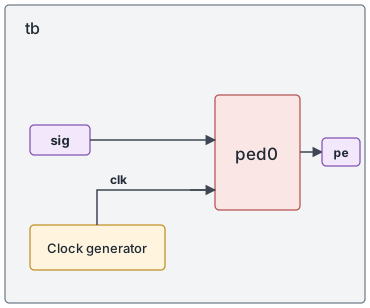
Verilog Testbench Components
A testbench is built from a few standard parts:
- DUT (Design Under Test): the module being verified. It can be anything from a simple adder to a complete processor.
- Testbench module: a separate top-level module with no ports, which contains everything else. It instantiates the DUT, generates its inputs and captures its outputs.
- Stimulus: the input values applied to the DUT over time, including clocks and resets. Stimulus is usually organized in functions and tasks so that it can be reused, and it should cover normal operation as well as corner cases.
- Connections: testbench signals connected to the DUT ports through module instantiation. Inputs are driven from
regvariables, and outputs are observed throughwirenets. - Checker: code that compares the DUT outputs with the expected values and reports any mismatch. A testbench with a checker is called self-checking, because it decides by itself whether the test passed.
Testbench code is only simulated, never synthesized. It can therefore use constructs that have no hardware equivalent, such as initial blocks, # delays, $random and $display.
Synthesis result: None for the testbench itself. Only the DUT goes through synthesis. This is why the DUT must be written in synthesizable RTL, while the testbench is free to use any simulation construct.
Verilog Testbench Example
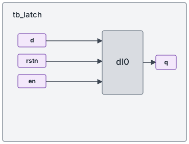
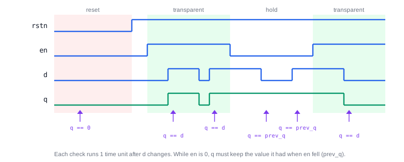
As an example, we will verify a D latch with an active-low reset. While rstn is 0, the output q is 0. Otherwise, q follows d while en is 1, and holds its last value while en is 0.
module d_latch (  input d,
                  input en,
                  input rstn,
                  output reg q);

   always @ (en or rstn or d) begin
      if (!rstn) begin
         q <= 0;
      end else begin
         if (en) begin
            q <= d;
         end
      end
   end
endmodule
Synthesis result: Because q is not assigned when rstn = 1 and en = 0, synthesis infers a level-sensitive latch with an asynchronous clear, not a flip-flop.
Writing the testbench takes six steps:
- Declare the testbench module
- Declare the signals that connect to the DUT
- Instantiate the DUT
- Initialize the inputs
- Write the stimulus
- Write the checker
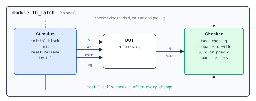
Step 1: Declare the testbench module
The top-level testbench module does not need any ports, because nothing outside it connects to it. It is usually called tb or tb_top, but any name works.
// Note that top level testbench module does not need any IO ports and
// hence can be empty and is usually called "tb" or "tb_top", but it can be
// named anything.

module tb_latch;

  // All testbench code goes inside this module

endmodule
Step 2: Declare the signals
Every DUT input needs a reg in the testbench, because its value is assigned from procedural blocks. Every DUT output needs a wire, because it is driven by the DUT. A few extra variables are needed for the stimulus and the checker.
reg     d;          // To drive input "d" of the DUT
reg     en;         // To drive input "en" of the DUT
reg     rstn;       // To drive input "rstn" of the DUT

reg     prev_q;     // To ensure q has not changed when en=0

wire    q;          // To tap output "q" from DUT

integer i;          // Loop counter
integer delay;      // Random delays used by the stimulus
integer delay2;
integer errors;     // Number of mismatches found by the checker
Step 3: Instantiate the DUT
Instantiate the design and connect each port to the matching testbench signal. Named connections such as .d(d) make the code independent of the port order.
d_latch u0 ( .d    (d),
             .en   (en),
             .rstn (rstn),
             .q    (q)
           );
Step 4: Initialize the inputs
All reg variables start as x at time 0. Give every DUT input a known value before the test starts, otherwise the DUT may produce x outputs. Placing the initialization in a task lets the main initial block call it by name.
task init;
  begin
    d      <= 0;
    en     <= 0;
    rstn   <= 0;      // Start with reset applied
    errors  = 0;
  end
endtask
Step 5: Write the stimulus
The stimulus releases the reset, then toggles en and changes d after random delays. After every change it waits 1 time unit for the DUT to respond, calls the checker, and saves the current q in prev_q for the next check.
task reset_release;
  // Release reset
  #10 rstn <= 1;
endtask

task test_1;
  // Randomly change d and enable
  for (i = 0; i < 20; i = i + 1) begin
    delay  = 1 + {$random} % 8;     // 1 to 8 time units
    delay2 = 1 + {$random} % 8;
    #(delay2) en <= ~en;
    #(delay)  d  <= $random;

    // Check output value for given inputs
    #1 check_q;
    prev_q = q;
  end
endtask

initial begin
  init;
  #5 check_q;            // Check during reset
  reset_release;
  prev_q = q;
  test_1;
  $display ("Test complete: %0d errors", errors);
  $finish;
end
Two details matter here. {$random} turns the signed 32-bit result of $random into an unsigned value, so % 8 always gives 0 to 7 and never a negative or huge delay. And the delays start at 1, so en and d never change in the same time step, which would make the result depend on the order of events.
Step 6: Write the checker
The checker encodes the specification of the latch: what q must be in each of the three situations. It reports every mismatch with the simulation time and counts it.
task check_q;
  begin
    if (!rstn) begin
      if (q !== 0) begin
        $display ("T=%0t ERROR: q is not 0 during reset", $time);
        errors = errors + 1;
      end
    end else if (en) begin
      if (q !== d) begin
        $display ("T=%0t ERROR: q does not follow d when en is high", $time);
        errors = errors + 1;
      end
    end else begin
      if (q !== prev_q) begin
        $display ("T=%0t ERROR: q does not hold its value when en is low", $time);
        errors = errors + 1;
      end
    end
  end
endtask
The comparisons use !== instead of !=. If q were x, q != d would give x, which an if treats as false, so the error would never be reported. !== compares x and z bits exactly and gives a clean 1 or 0.
Complete testbench
Putting all six steps together gives the complete testbench:
module tb_latch;
  reg     d, en, rstn;
  reg     prev_q;
  wire    q;
  integer i, delay, delay2, errors;

  d_latch u0 (.d(d), .en(en), .rstn(rstn), .q(q));

  task init;
    begin
      d <= 0; en <= 0; rstn <= 0;
      errors = 0;
    end
  endtask

  task reset_release;
    #10 rstn <= 1;
  endtask

  task check_q;
    begin
      if (!rstn) begin
        if (q !== 0) begin
          $display ("T=%0t ERROR: q is not 0 during reset", $time);
          errors = errors + 1;
        end
      end else if (en) begin
        if (q !== d) begin
          $display ("T=%0t ERROR: q does not follow d when en is high", $time);
          errors = errors + 1;
        end
      end else begin
        if (q !== prev_q) begin
          $display ("T=%0t ERROR: q does not hold its value when en is low", $time);
          errors = errors + 1;
        end
      end
    end
  endtask

  task test_1;
    for (i = 0; i < 20; i = i + 1) begin
      delay  = 1 + {$random} % 8;
      delay2 = 1 + {$random} % 8;
      #(delay2) en <= ~en;
      #(delay)  d  <= $random;
      #1 check_q;
      prev_q = q;
    end
  endtask

  initial begin
    init;
    #5 check_q;
    reset_release;
    prev_q = q;
    test_1;
    $display ("Test complete: %0d errors", errors);
    $finish;
  end
endmodule
With the correct latch, the only line printed is the summary:
Test complete: 0 errors
To see the checker at work, introduce a bug in the DUT, for example change q <= d; to q <= ~d;. The testbench then prints an ERROR line with the time of each check where en is 1, followed by a non-zero error count.
Quick Check
Suppose the DUT had a bug that made q follow d even while en is 0. Which branch of check_q would catch it, and why is prev_q needed?
Show Answer
The last branch, for rstn = 1 and en = 0. When d changes while en is 0, a buggy q changes too, and no longer equals prev_q, the value saved at the previous check. Without prev_q, the checker would have nothing to compare against: in hold mode the correct output depends on the past, not on the current inputs.
Quick Check
Why does test_1 wait #1 before calling check_q, instead of checking right after d <= $random?
Show Answer
d <= $random is a nonblocking assignment, so d only changes at the end of the time step, and the latch updates q after that. Checking in the same time step would compare the old q with the old d. Waiting 1 time unit lets the DUT settle before its output is checked.
Regressions Need Self-Checking Tests
A chip project runs thousands of tests every night, and nobody can look at thousands of waveforms. Every test therefore ends with a clear pass or fail message, like the error count above, and scripts collect these results into a report. A test that only prints values for a human to inspect is useful while writing it, but it cannot be part of a regression.
Reference Models
For larger designs, the checker does not hard-code the expected value as check_q does. Instead, the testbench contains a reference model: a simple behavioral description of what the design should do, often written at a higher level or in another language. The same stimulus goes to both the DUT and the model, and a scoreboard compares their outputs.
Testbenches like this one let designers find flaws in a design long before it reaches physical implementation. For more examples, see the testbenches for the 4-bit counter, the full adder and the single port RAM.
Common Beginner Mistakes
Mistake #1: Comparing with != in the checker
Wrong: if (q != d) $display("ERROR");
Right: if (q !== d) $display("ERROR");
Why? If q is x, for example because the DUT is not driving it, q != d is x, and the if takes the false branch. The checker silently passes a completely broken design. !== treats x as a value of its own, so the mismatch is reported.
Mistake #2: Calling a function as a statement
Wrong: Writing the checker as function checker(...) and calling it as checker(d, en, rstn, q);
Right: Write the checker as a task, such as task check_q, and call it as a statement
Why? In Verilog, a function returns a value and can only be called inside an expression, so calling it on its own line is an error. Also, checker is a keyword in SystemVerilog, so a function with that name fails to compile in any SystemVerilog-capable simulator.
Mistake #3: Leaving the DUT inputs uninitialized
Wrong: Starting the stimulus without assigning d, en and rstn first
Right: Give every input a known value at time 0, as the init task does
Why? reg variables start at x. An x on an input spreads through the DUT, so outputs become x, and checks either fail for the wrong reason or, with !=, pass for the wrong reason.
Mistake #4: Using raw $random as a delay
Wrong: delay = $random; #(delay) en <= ~en;
Right: delay = 1 + {$random} % 8;
Why? $random returns any 32-bit signed value. A negative value is interpreted as a huge unsigned delay, so the test can wait for billions of time units and appear to hang. Limiting the range keeps the test short and predictable.
Mistake #5: Port names that do not match the DUT
Wrong: dut u0 (.d(d), .clk(clk), .rstn(rstn), .q(q)); for the d_latch module
Right: d_latch u0 (.d(d), .en(en), .rstn(rstn), .q(q));
Why? The module name in the instantiation must be the name of the DUT module, and every named port must exist in it. A latch has no clk port, and leaving out .en would leave the enable floating at z.
Practice Exercise
Challenge: Self-Checking Testbench for a 2:1 Mux
Write a self-checking testbench for this multiplexer. Apply all 8 combinations of a, b and sel, check the output after each one, and print the number of errors at the end.
module mux2 (input a, b, sel, output y);
  assign y = sel ? b : a;
endmodule
Hint
A 3-bit loop counter can drive all inputs at once with {a, b, sel} = i;. The expected value is sel ? b : a, computed in the testbench. Compare with !== after a short delay.
Solution
module tb_mux2;
  reg  a, b, sel;
  wire y;
  reg  exp_y;
  integer i, errors;

  mux2 u0 (.a(a), .b(b), .sel(sel), .y(y));

  initial begin
    errors = 0;
    for (i = 0; i < 8; i = i + 1) begin
      {a, b, sel} = i;
      exp_y = sel ? b : a;     // Expected value from the specification
      #1;
      if (y !== exp_y) begin
        $display ("T=%0t ERROR: a=%b b=%b sel=%b y=%b expected %b",
                  $time, a, b, sel, y, exp_y);
        errors = errors + 1;
      end
    end
    $display ("Test complete: %0d errors", errors);
    $finish;
  end
endmodule
With a correct mux, the output is Test complete: 0 errors. Because the mux is combinational and has only 3 inputs, this exhaustive test covers every possible input. For a design with many inputs or internal state, exhaustive testing is impossible, which is why random stimulus like the one in test_1 is used.
Summary
In this tutorial, you learned:
- A testbench is a module with no ports that instantiates the DUT, drives its inputs and checks its outputs
- DUT inputs are driven from
regvariables and outputs are read throughwirenets - Inputs must be initialized at time 0, because
regvariables start asx - Tasks organize the stimulus into reusable steps such as
init,reset_releaseandtest_1 - A self-checking testbench compares outputs with expected values, using
!==so thatxis caught, and reports a pass or fail result - Testbench code is never synthesized, so it can use delays,
$randomand system tasks freely
