
A ring counter is a shift register whose last output is fed back to its first input, so the bits circulate in a closed loop. It is loaded with a single 1 and all other bits 0, and on every clock edge that 1 moves one position. In Verilog, a ring counter is a register that rotates by one bit at each clock edge.
10 min read | Beginner Level
What You'll Learn
- How a ring counter circulates a single 1 and why it produces one-hot outputs
- Write a parameterized ring counter in Verilog and initialize it correctly
- What synthesis builds from it, and how it compares with binary and Johnson counters
- How to handle illegal states with a self-correcting ring counter
What Is a Ring Counter?
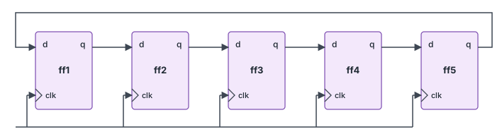
A ring counter is a shift register closed into a loop. On each clock edge, every flip-flop takes the value of its neighbor, and the bit that leaves one end of the register re-enters at the other end. The feedback is a plain wire: no inverter, adder or comparator is needed.
When the register holds a single 1, that 1 travels around the loop like a ball on a track, moving one position per clock. A ring counter with N flip-flops therefore has N states and repeats every N clock cycles, so it is a Mod-N counter, as described in Verilog Mod-N counter.
How It Works
The design in this article resets to 4'b0001 and shifts to the right, with bit 0 wrapping around into bit 3:
| Clock edge after reset | out[3:0] | Active bit |
|---|---|---|
| 0 (reset) | 0001 | out[0] |
| 1 | 1000 | out[3] |
| 2 | 0100 | out[2] |
| 3 | 0010 | out[1] |
| 4 | 0001 | out[0] (sequence repeats) |
Exactly one bit is 1 at any time. This is called one-hot encoding: each state has its own flip-flop, and the state is identified by which flip-flop holds the 1. A ring counter is the simplest one-hot circuit, and one-hot state machines use the same idea with more complex transitions between states. See Verilog FSM.
Because each output bit is high for exactly one state, no decoder is needed. A binary counter needs a comparator to detect "state 2", while a ring counter provides it directly as out[2].
Shift Direction & Initialization
The shift direction depends only on how the flip-flops are connected. Shifting right, as in this design, and shifting left are both valid. Choose the direction that makes the order of the output bits most convenient for the logic that uses them.
Initialization is the critical part. The register must start with exactly one 1:
- All zeros: if the register starts at
0000, rotating it gives0000forever. The counter is stuck. - More than one 1: all the 1s circulate together. The counter still repeats, but the outputs are no longer one-hot, and any logic that assumes a single active bit fails.
The reset therefore loads a fixed one-hot value, here 1, which sets bit 0 and clears the others.
Quick Check
Q: If the reset loaded 4'b0011 instead of 1, what sequence would this design produce?
Show Answer
0011, 1001, 1100, 0110, then 0011 again. Both 1s rotate together, so the period is still 4, but two outputs are high in every state and the counter is no longer one-hot.
Design
module ring_ctr  #(parameter WIDTH=4)
  (
	input clk,
	input rstn,                       // Active-low synchronous reset
  	output reg [WIDTH-1:0] out
  );

  integer i;

  always @ (posedge clk) begin
      if (!rstn)
         out <= 1;                    // Load a single 1 in bit 0, zeros elsewhere
      else begin
        out[WIDTH-1] <= out[0];       // Feedback: bit 0 wraps around to the MSB
        for (i = 0; i < WIDTH-1; i=i+1) begin
          out[i] <= out[i+1];         // Every other bit takes its left neighbor
        end
      end
  end
endmodule
The for loop and the feedback assignment together rotate out right by one bit. The same rotation can be written in one line with a concatenation: out <= {out[0], out[WIDTH-1:1]};. Non-blocking assignments are required, so that every bit captures its neighbor's value from before the clock edge.
Synthesis result: The tool builds WIDTH flip-flops connected in a loop, with the reset forcing bit 0 to 1 and the others to 0. Between the flip-flops there is only wiring and the reset gating, no adder or comparator. This makes the ring counter one of the fastest counters possible, since the path from one flip-flop to the next contains almost no logic.
Where are Ring Counters Used?
Multiplexed LED and seven-segment displays turn on one digit at a time, cycling fast enough that all digits appear lit. A ring counter drives the digit-select lines: each output enables one digit, and only one is active in each time slot. Keypad scanners use the same pattern to drive one row of keys at a time.
Testbench
The testbench uses a 20 ns clock period, holds reset for two clock edges, then runs for 15 more edges.
module tb;
  parameter WIDTH = 4;

  reg clk;
  reg rstn;
  wire [WIDTH-1:0] out;

  // Pass WIDTH to the design so both use the same value
  ring_ctr #(.WIDTH(WIDTH)) u0 (.clk (clk),
                .rstn (rstn),
                .out (out));

  always #10 clk = ~clk;        // Rising edges at 10, 30, 50, ...

  initial begin
    {clk, rstn} <= 0;

    $monitor ("T=%0t out=%b", $time, out);
    repeat (2) @(posedge clk);
    rstn <= 1;
    repeat (15) @(posedge clk);
    $finish;
  end
endmodule
ncsim> run
T=0 out=xxxx
T=10 out=0001
T=50 out=1000
T=70 out=0100
T=90 out=0010
T=110 out=0001
T=130 out=1000
T=150 out=0100
T=170 out=0010
T=190 out=0001
T=210 out=1000
T=230 out=0100
T=250 out=0010
T=270 out=0001
T=290 out=1000
T=310 out=0100
Simulation complete via $finish(1) at time 330 NS + 0
Reset loads 0001 at the first edge (10 ns). At 30 ns reset is still active, so the value does not change and $monitor prints nothing. From 50 ns, the 1 moves right by one position on every edge and wraps from bit 0 back to bit 3, repeating every four edges (80 ns).
Ring vs Johnson vs Binary Counter
| Binary counter | Ring counter | Johnson counter | |
|---|---|---|---|
| States with N flip-flops | 2N | N | 2N |
| Flip-flops for 8 states | 3 | 8 | 4 |
| Logic between flip-flops | Incrementer | None (wire) | One inverter |
| Decoding a state | Comparator on all bits | None: one bit per state | 2-input gate per state |
| Unused states | None | 2N - N | 2N - 2N |
A ring counter spends more flip-flops per state than any other counter, but it needs no decoding logic and has the shortest timing path. It suits a small number of states where speed or glitch-free state outputs matter. The Johnson counter doubles the number of states by inverting the feedback.
Round-Robin Arbiters
When several requesters share a bus or memory port, a round-robin arbiter gives each one a turn in fixed order. A one-hot ring register stores whose turn has the highest priority, and it rotates by one position after each grant, so no requester can be starved.
Stepper Motor Phase Control
A stepper motor turns one step each time the next coil in its sequence is energized. A 4-bit ring counter driving the four coil phases produces the full-step sequence directly, with one coil on at a time, and reversing the shift direction reverses the motor.
Common Beginner Mistakes
Mistake #1: Resetting the register to zero
Wrong: if (!rstn) out <= 0;
Right: if (!rstn) out <= 1; (or any other one-hot value)
Why? Rotating 0000 gives 0000, so the counter never leaves that state. Simulation shows a constant 0 on every output, with no error message.
Mistake #2: Blocking assignments in the shift
Wrong: out[WIDTH-1] = out[0]; for (...) out[i] = out[i+1];
Right: Use non-blocking assignments (<=) for every bit
Why? With blocking assignments, out[WIDTH-1] is overwritten first, so when the loop later copies out[WIDTH-1] into out[WIDTH-2], it copies the new value instead of the old one. From 0001, the next state is 1100: the single 1 is duplicated and the outputs are no longer one-hot. See Verilog Blocking & Non-Blocking.
Mistake #3: Running the loop one bit too far
Wrong: for (i = 0; i < WIDTH; i = i + 1) out[i] <= out[i+1];
Right: for (i = 0; i < WIDTH-1; i = i + 1) out[i] <= out[i+1];
Why? In the last iteration, out[i+1] is out[WIDTH], which does not exist. Reading it returns x in simulation, and that assignment overrides the feedback to the MSB, so an x enters the ring and spreads to every bit.
Mistake #4: Assuming the counter recovers from a bad state
Wrong: Relying on reset alone in a design where a glitch or radiation upset could change a bit
Right: Use a self-correcting feedback, as in the practice exercise below
Why? A plain ring counter keeps whatever pattern it holds. If an upset adds a second 1 or clears the only 1, the wrong pattern circulates until the next reset, which in a running system may never come.
Practice Exercise
Challenge: Self-Correcting Ring Counter
Modify the ring counter so that it returns to a valid one-hot state from any starting value, including 0000 and patterns with several 1s, within a few clock cycles and without a reset. Keep the right-shift direction and the normal sequence 0001, 1000, 0100, 0010.
Hint
Instead of feeding out[0] back to the MSB, feed a 1 to the MSB only when all the bits that are about to shift right, out[WIDTH-1:1], are 0. Extra 1s then shift out of bit 0 and are never fed back.
Solution
module ring_ctr_sc #(parameter WIDTH = 4) (
  input                  clk,
  input                  rstn,
  output reg [WIDTH-1:0] out
);

  always @(posedge clk) begin
    if (!rstn)
      out <= 1;
    else
      // MSB gets a 1 only when bits [WIDTH-1:1] are all zero;
      // all other bits shift right as before
      out <= {~|out[WIDTH-1:1], out[WIDTH-1:1]};
  end

endmodule
From 0001, bits [3:1] are all 0, so a 1 enters the MSB and the next state is 1000, the same as the plain ring counter. From 0000, a 1 is inserted on the next edge. From a pattern with extra 1s, no new 1 is inserted until the extra ones have shifted out of bit 0. For WIDTH = 4, every one of the 16 starting values reaches the normal sequence within 3 clock cycles. The cost is one WIDTH-1 input NOR gate in the feedback path.
Summary
In this tutorial, you learned:
- A ring counter is a shift register with its output fed back to its input, circulating a single 1
- N flip-flops give N states, with exactly one output high in each state (one-hot)
- The register must be initialized with exactly one 1; all zeros locks it up
- The rotate can be written with a loop or as
out <= {out[0], out[WIDTH-1:1]}, always with non-blocking assignments - Synthesis builds only flip-flops and wiring, which makes ring counters very fast and decoding free
- Ring counters use more flip-flops per state than binary or Johnson counters
- A self-correcting feedback lets the counter recover from illegal states without a reset
