
The Verilog initial block executes once at the start of simulation (time 0) and is essential for testbench initialization, setting up test scenarios, and driving stimulus. Unlike always blocks which run continuously, initial blocks are strictly for simulation and do not synthesize into hardware.
8 min read | Beginner
What You'll Learn
- Understand when and why to use
initialblocks for testbench initialization - Apply delays within
initialblocks to create sequential stimulus - Use multiple
initialblocks running in parallel for complex test scenarios - Recognize that
initialblocks are simulation-only and non-synthesizable
A set of Verilog statements are usually executed sequentially in a simulation. These statements are placed inside a procedural block. There are mainly two types of procedural blocks in Verilog - initial and always.
Syntax
// Single statement (no begin/end needed)
initial
    [single statement]

// Multiple statements (requires begin/end)
initial begin
    [statement 1]
    [statement 2]
    ...
    [statement N]
end
What is the initial block used for?
An initial block is not synthesizable and hence cannot be converted into a hardware schematic with digital elements. Hence initial blocks do not serve much purpose than to be used in simulations. These blocks are primarily used to initialize variables and drive design ports with specific values.
Non-Synthesizable: initial blocks are for simulation only. Synthesis tools ignore them completely. Use initial in testbenches for initialization and stimulus, not in RTL design modules.
Common Uses in Testbenches:
- Initialize signals: Set registers and memories to known values at time 0
- Generate stimulus: Apply test vectors to the design under test (DUT)
- Clock generation: Start clock generation processes (though
alwaysis more common for continuous clocks) - Open files: Initialize file handles for reading test vectors or writing results
- Control simulation: Set timeouts using
$finishto end simulation
When does an initial block start and end?
An initial block is started at the beginning of a simulation at time 0 unit. This block will be executed only once during the entire simulation. Execution of an initial block finishes once all the statements within the block are executed.
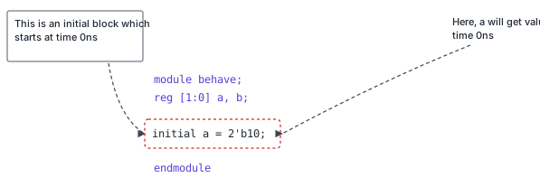
The image shown above has a module called behave which has two internal signals called a and b. The initial block has only one statement and hence it is not necessary to place the statement within begin and end. This statement assigns the value 2'b10 to a when the initial block is started at time 0 units.
If your initial block contains only one statement, you can omit begin/end. For multiple statements, always use begin/end to group them.
What happens if there is a delay element?
The code shown below has an additional statement that assigns some value to the signal b. However this happens only after 10 time units from execution of previous statement. This means that a is assigned first with the given value and then after 10 time units, b is assigned to 0.
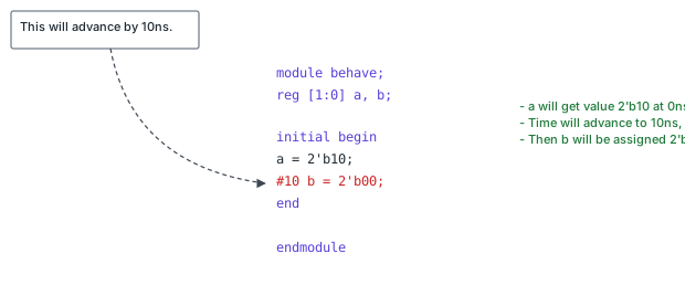
Sequential Execution with Delays: Statements in an initial block execute sequentially. Delay operators (#N) pause execution for N time units before continuing to the next statement.
Example with Delays:
module tb;
    reg [1:0] a, b;

    initial begin
        a = 2'b10;              // Time 0: a assigned immediately
        #10 b = 2'b00;          // Time 10: b assigned after 10-unit delay
        #20 a = 2'b01;          // Time 30: a reassigned after additional 20 units
        #5 $display("Time=%0t a=%b b=%b", $time, a, b); // Time 35: display values
    end
endmodule
$ /usr/bin/vvp simulation +random_seed+1945140138
Time=35 a=01 b=00
Execution Timeline:
- Time 0:
a = 2'b10 - Time 10:
b = 2'b00 - Time 30:
a = 2'b01 - Time 35: Display shows
Time=35 a=01 b=00
How many initial blocks are allowed in a module?
There are no limits to the number of initial blocks that can be defined inside a module.
The code shown below has three initial blocks all of which are started at the same time and run in parallel. However, depending on the statements and the delays within each initial block, the time taken to finish the block may vary.
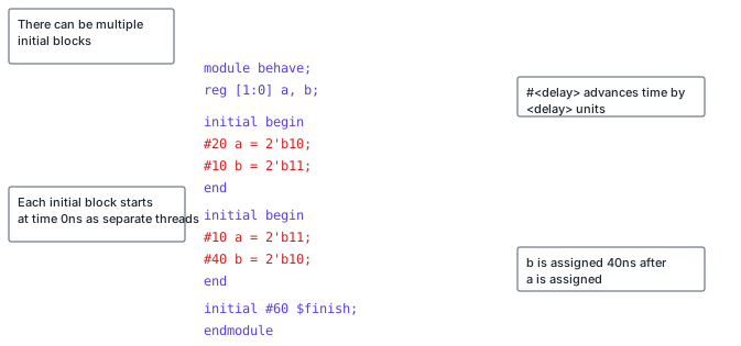
In this example, the first block has a delay of 20 units, while the second has a total delay of 50 units (10 + 40) and the last block has a delay of 60 units. Hence the simulation takes 60 time units to complete since there is atleast one initial block still running until 60 time units.
Parallel Execution: All initial blocks start simultaneously at time 0 and run independently in parallel. The simulation continues until all initial and always blocks complete or $finish is called.
Example with Multiple Initial Blocks:
module tb_parallel;
 reg clk = 0;
 reg [7:0] data;

 // Initial block 1: Generate clock (runs for 50 time units)
 initial begin
 repeat (10) begin
 #5 clk = ~clk; // Toggle clock every 5 units
 end
 $display("Block 1 finished at time %0t", $time); // Time 50
 end

 // Initial block 2: Apply test data (runs for 30 time units)
 initial begin
 data = 8'h00;
 #10 data = 8'hAA; // Time 10
 #10 data = 8'h55; // Time 20
 #10 data = 8'hFF; // Time 30
 $display("Block 2 finished at time %0t", $time); // Time 30
 end

 // Initial block 3: Monitor and finish (controls simulation end)
 initial begin
 $monitor("Time=%0t clk=%b data=%h", $time, clk, data);
 #60 $finish; // End simulation at time 60
 end
endmodule
$ /usr/bin/vvp simulation +random_seed+998037043
Time=0 clk=0 data=00
Time=5 clk=1 data=00
Time=10 clk=0 data=aa
Time=15 clk=1 data=aa
Time=20 clk=0 data=55
Time=25 clk=1 data=55
Block 2 finished at time 30
Time=30 clk=0 data=ff
Time=35 clk=1 data=ff
Time=40 clk=0 data=ff
Time=45 clk=1 data=ff
Block 1 finished at time 50
Time=50 clk=0 data=ff
testbench.v:25: $finish called at 60 (1ns)
Execution:
- All three blocks start at time 0
- Block 1 toggles clock every 5 units, finishes at time 50
- Block 2 changes data values, finishes at time 30
- Block 3 monitors signals and ends simulation at time 60
Controlling simulation end with $finish
$finish is a Verilog system task that tells the simulator to terminate the current simulation.
If the last block had a delay of 30 time units like shown below, the simulation would have ended at 30 time units thereby killing all the other initial blocks that are active at that time.
initial begin
    #30 $finish; // Terminates entire simulation at time 30
end
$ /usr/bin/vvp simulation +random_seed+1644377346
testbench.v:24: $finish called at 30 (1ns)
Block 2 finished at time 30
$finish Terminates All Blocks:
When$finish executes, the entire simulation stops immediately, terminating all active initial and always blocks. Use this to set simulation timeouts or end tests after stimulus completes.Synthesis
An initial block is not synthesizable. Synthesis tools completely ignore initial blocks during RTL-to-gate conversion.
Testbench vs RTL:
- Testbench: Use
initialblocks freely for initialization and stimulus generation - RTL (Design): Never use
initialblocks - hardware has no concept of "time 0 initialization". Use reset signals instead
Real-World Application
SystemVerilog and UVM testbenches in major semiconductor companies use initial blocks to assign values to variables, and setup configuration objects to database. The UVM test starts from an initial block that calls run_test() to launch the verification environment. Complex testbenches may have multiple initial blocks: one for clock generation, one for reset sequencing, one for loading memory models, and one for controlling test execution. This parallel initialization speeds up test setup and improves code organization.
initial vs always Blocks
| Feature | initial Block | always Block |
|---|---|---|
| Execution | Runs once at time 0 | Runs continuously (loops forever) |
| End Condition | Finishes when last statement executes | Never ends (runs entire simulation) |
| Synthesizable | No (simulation only) | Yes (when properly coded) |
| Use Case | Testbench initialization, stimulus | Hardware behavior (RTL), continuous processes |
| Sensitivity List | Not applicable | Required for combinational/sequential logic |
| Multiple Allowed | Yes (all run in parallel) | Yes (all run in parallel) |
Common Beginner Mistakes
Mistake #1: Using initial blocks in RTL design modules
module counter (input clk, output reg [3:0] count);
    initial count = 0; // WRONG: Not synthesizable!

    always @(posedge clk)
        count <= count + 1;
endmodule
Why it's problematic: initial blocks are simulation-only constructs. In real hardware, registers power up to unknown values. Synthesis tools ignore initial blocks, so count won't be initialized to 0 in the fabricated chip, causing unpredictable behavior.
Best Practice: Use a reset signal in RTL:
module counter (input clk, input reset_n, output reg [3:0] count);
    always @(posedge clk or negedge reset_n) begin
        if (!reset_n)
            count <= 4'b0000; // Hardware reset
        else
            count <= count + 1;
        end
endmodule
Mistake #2: Forgetting delays in stimulus, causing race conditions
initial begin
    reset = 1;
    reset = 0; // Executes right after reset=1 in the same time step, so reset=1 lasts for zero time
    data = 8'hAA;
end
Why it's problematic: Without delays, all assignments happen at time 0 simultaneously. Both statements execute at the same time, so reset ends at 0 without ever being 1 for any simulation time. The DUT never sees the reset pulse.
Best Practice: Use explicit delays:
initial begin
    reset = 1;
    #10 reset = 0; // Deassert reset after 10 time units
    #5 data = 8'hAA; // Apply data after reset stabilizes
end
Mistake #3: Not using $finish to end simulation
always #5 clk = ~clk; // Clock runs forever

initial begin
    #100 data = 8'hFF; // Apply data, but simulation never ends
end
Why it's problematic: The always block keeps the simulation running indefinitely causing clock to be toggled after 5 time units. Without $finish, the simulation must be manually stopped or killed, else it simply wastes time and resources.
Best Practice: Add a timeout block with $finish:
always #5 clk = ~clk;

initial begin
    #100 data = 8'hFF;
end

initial begin
    #200 $finish; // End simulation after test completes
end
Mistake #4: Confusing blocking (=) and non-blocking (<=) in initial blocks
initial begin
    a <= 1; // Non-blocking: scheduled for end of time step
    b = a; // Blocking: executes immediately (b gets OLD value of a!)
end
Why it's problematic: Mixing blocking and non-blocking assignments in initial blocks creates timing ambiguity. b = a executes before a <= 1 takes effect, so b gets the previous value of a, not 1.
Best Practice: Use blocking assignments (=) in initial blocks for sequential stimulus:
initial begin
    a = 1; // Blocking: a is updated immediately
    b = a; // Blocking: b gets current value of a (which is 1)
end
Summary
In this tutorial, you learned:
initialblocks execute once at time 0 and are used exclusively in testbenches for initialization and stimulus- Statements in
initialblocks execute sequentially, with delays (#N) pausing execution between statements - Multiple
initialblocks run in parallel, all starting at time 0, enabling modular testbench construction initialblocks are non-synthesizable; use reset signals in RTL designs instead ofinitialfor initialization$finishterminates the entire simulation, stopping all activeinitialandalwaysblocks immediately- Use blocking assignments (
=) ininitialblocks for clear sequential execution in testbenches
