
A Johnson counter, also called a twisted ring counter, is a shift register whose last output is inverted and fed back to its first input. With N flip-flops it cycles through 2N states, filling the register with 1s and then clearing it with 0s, one bit per clock. In Verilog, it is a register that shifts by one bit each clock edge and takes the complement of the outgoing bit as its new input.
10 min read | Beginner Level
What You'll Learn
- How inverted feedback gives a Johnson counter 2N states from N flip-flops
- Write a parameterized Johnson counter in Verilog and read its state sequence
- Why Johnson counters give glitch-free outputs and decode every state with one 2-input gate
- How invalid states arise and how to make the counter self-correcting
What is a Johnson Counter ?
A Johnson counter is a chain of flip-flops connected as a shift register, with a feedback path from the last flip-flop back to the first. The difference from a ring counter is a single inverter: the value fed back is the complement of the bit leaving the register. That twist in the feedback is where the name "twisted ring counter" comes from. The counter is also known as a creeping-code counter, because its state changes by only one bit at a time.
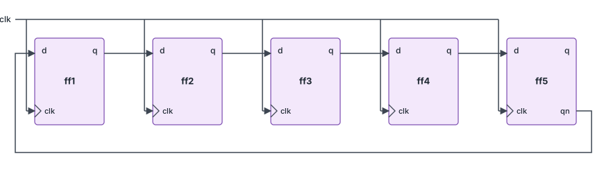
The Ring Counter vs. The Johnson Counter
A ring counter with N flip-flops circulates a single 1 and has N states. A Johnson counter uses the same chain, but because the feedback is inverted, the register first fills up with 1s, one per clock, and then empties out with 0s. This gives 2N states from the same N flip-flops.
| Ring counter | Johnson counter | |
|---|---|---|
| Feedback | Last output, unchanged | Last output, inverted |
| States with N flip-flops | N | 2N |
| Bits changing per clock | 2 (one turns off, the next turns on) | 1 |
| State decoding | None: one bit per state | One 2-input AND gate per state |
| Valid reset values | Any one-hot value | Any value in the sequence, such as all zeros |
How It Works: Step by Step
The design in this article shifts right: on each clock edge, every bit moves one position toward bit 0, and the new bit 3 is the inverse of the old bit 0. The reset loads 4'b0001, which is one of the eight valid states. Starting there, a 4-bit Johnson counter goes through this sequence:
| Clock edge after reset | out[3:0] | New bit 3 = ~out[0] |
|---|---|---|
| 0 (reset) | 0001 | |
| 1 | 0000 | ~1 = 0 |
| 2 | 1000 | ~0 = 1 |
| 3 | 1100 | ~0 = 1 |
| 4 | 1110 | ~0 = 1 |
| 5 | 1111 | ~0 = 1 |
| 6 | 0111 | ~1 = 0 |
| 7 | 0011 | ~1 = 0 |
| 8 | 0001 | ~1 = 0 (sequence repeats) |
1s enter from the left until the register is full, then 0s enter until it is empty. There are 8 distinct states, so this is a Mod-8 counter built from 4 flip-flops. Each output bit is high for 4 consecutive clocks and low for the next 4, so every bit is a square wave at 1/8 of the clock frequency with a 50% duty cycle.
What are Johnson Counters used for ?
A Johnson counter uses more flip-flops than a binary counter for the same number of states, but it has two properties that binary counters lack.
Glitch Free Outputs
In a binary counter, several bits can change on the same clock edge. Going from 0111 to 1000, all four bits change. Because they never change at exactly the same instant, logic that decodes the count can briefly see wrong values and produce short glitches. In a Johnson counter, exactly one bit changes on every clock edge, so the decoded outputs move cleanly from one state to the next.
Easy Decoding
Every state of a Johnson counter can be identified by looking at just two neighboring bits, so each state needs only one 2-input AND gate, whatever the counter width. For the 4-bit counter above:
| State | Decode term |
|---|---|
| 0000 | ~out[3] & ~out[0] |
| 1000 | out[3] & ~out[2] |
| 1100 | out[2] & ~out[1] |
| 1110 | out[1] & ~out[0] |
| 1111 | out[3] & out[0] |
| 0111 | ~out[3] & out[2] |
| 0011 | ~out[2] & out[1] |
| 0001 | ~out[1] & out[0] |
The pattern is easy to see: each state is the point where a 1 meets a 0 in the register, or, for the all-zeros and all-ones states, where the two ends of the register match. A binary counter would need a 4-input comparison for each of its states.
Quick Check
Q: How many flip-flops does a Johnson counter need for 10 states, and how does that compare with a binary counter and a ring counter?
Show Answer
5 flip-flops, since a Johnson counter has 2N states. A binary counter needs 4 ($clog2(10)) and a ring counter needs 10. A 5-bit Johnson counter is the classic decade counter used in counter/divider chips with ten decoded outputs.
Common Usecases
- Clock dividers and timing generators: each output is a 50% duty-cycle square wave at clk / 2N
- Sequence generators: the decoded outputs fire in a fixed order, one per clock, without glitches
- State machine encoding: a sequence of states that always advance in order can be encoded as a Johnson count to keep the next-state and output logic small
- Multi-phase signal generators: the outputs are copies of the same waveform, each delayed by one clock period, which gives evenly spaced phases
Where are Johnson Counters Used?
Quadrature generators for radio receivers need two copies of a signal, shifted by a quarter of a period. A 2-bit Johnson counter running at four times the target frequency produces exactly that: its two outputs are 50% duty-cycle square waves at clk / 4, offset from each other by one clock, which is 90 degrees. The same idea with more bits produces multi-phase clocks for power converters and motor drivers.
The Self-Correcting Problem
A 4-bit register has 16 possible patterns, but only 8 belong to the Johnson sequence. The other 8 form a second, separate loop. With the basic feedback, a counter that enters one of them, from a power-up with no reset or an upset that flips a bit, stays in that loop forever:
0010 -> 1001 -> 0100 -> 1010 -> 1101 -> 0110 -> 1011 -> 0101 -> 0010 -> ...
There are two remedies:
- Reset: always reset the register to a valid state, such as
0001or0000. This is enough when the counter is always reset before use, and every design should include it. - Self-correcting feedback: change the feedback so that every invalid pattern leads back into the valid sequence, without a reset. For this 4-bit design, using
~out[0] & (out[2] | ~out[1])as the new MSB keeps the valid sequence unchanged and returns any invalid pattern to it within 5 clock cycles.
Robust Counters in Harsh Environments
Electronics in vehicles, industrial controllers and satellites can see bit flips from electrical noise or radiation. Counters in these designs either use self-correcting feedback or add logic that detects invalid patterns and forces a valid state, so that a single upset cannot leave a timing sequence stuck in the wrong loop.
Design
module johnson_ctr #(parameter WIDTH=4)
  (
	input clk,
	input rstn,                       // Active-low synchronous reset
  	output reg [WIDTH-1:0] out
  );

  reg [$clog2(WIDTH):0] i;            // Loop variable, wide enough to reach WIDTH-1

  always @ (posedge clk) begin
      if (!rstn)
         out <= 1;                    // Reset to 0001, a valid Johnson state
      else begin
        out[WIDTH-1] <= ~out[0];      // Inverted feedback: the "twist"
        for (i = 0; i < WIDTH-1; i=i+1) begin
          out[i] <= out[i+1];         // Shift right by one bit
        end
      end
  end
endmodule
The only difference from the ring counter is the ~ in the feedback. The whole update can also be written in one line: out <= {~out[0], out[WIDTH-1:1]};.
Synthesis result: The tool builds WIDTH flip-flops connected as a shift register, plus one inverter from bit 0 to the MSB's input, and the reset gating. There is no adder or comparator, so the path between flip-flops is very short and the counter can run at almost the maximum clock frequency of the flip-flops themselves.
Testbench
The testbench uses a 20 ns clock period, holds reset for two clock edges, then runs for 15 more edges, which covers almost two full 8-state cycles.
module tb;
  parameter WIDTH = 4;

  reg clk;
  reg rstn;
  wire [WIDTH-1:0] out;

  // Pass WIDTH to the design so both use the same value
  johnson_ctr #(.WIDTH(WIDTH)) u0 (.clk (clk),
                .rstn (rstn),
                .out (out));

  always #10 clk = ~clk;        // Rising edges at 10, 30, 50, ...

  initial begin
    {clk, rstn} <= 0;

    $monitor ("T=%0t out=%b", $time, out);
    repeat (2) @(posedge clk);
    rstn <= 1;
    repeat (15) @(posedge clk);
    $finish;
  end
endmodule
$ /usr/bin/vvp simulation +random_seed+142378234
T=0 out=xxxx
T=10 out=0001
T=50 out=0000
T=70 out=1000
T=90 out=1100
T=110 out=1110
T=130 out=1111
T=150 out=0111
T=170 out=0011
T=190 out=0001
T=210 out=0000
T=230 out=1000
T=250 out=1100
T=270 out=1110
T=290 out=1111
T=310 out=0111
testbench.v:21: $finish called at 330 (1ns)
T=330 out=0011
Reset loads 0001 at 10 ns and is still active at 30 ns, so nothing changes there. From 50 ns the counter follows the table above, filling with 1s up to 1111 at 130 ns, emptying back to 0001 at 190 ns, and repeating. Each line differs from the previous one in exactly one bit.
Quick Check
Q: In the log, how long is out[3] high in each cycle, and what is its frequency relative to the clock?
Show Answer
80 ns, from 70 ns to 150 ns, followed by 80 ns low. The period is 160 ns, which is 8 clock periods of 20 ns, so out[3] is a 50% duty-cycle square wave at 1/8 of the clock frequency.
Decade Counter and Divider Chips
A 5-stage Johnson counter with its ten 2-input decode gates is the circuit inside common CMOS decade counter/divider chips. They provide ten decoded outputs that go high one after another, and are used for LED chasers, simple sequencers and dividing a clock by any number up to 10.
Common Beginner Mistakes
Mistake #1: Leaving out the inverter
Wrong: out[WIDTH-1] <= out[0];
Right: out[WIDTH-1] <= ~out[0];
Why? Without the inversion, the circuit is a ring counter. With the reset value 0001, it produces a 4-state one-hot sequence instead of the 8-state Johnson sequence. With a reset value of 0000, it would be stuck at zero.
Mistake #2: Resetting to a state outside the sequence
Wrong: if (!rstn) out <= 4'b0101;
Right: Reset to a valid Johnson state, such as 4'b0000 or 4'b0001
Why? 0101 belongs to the invalid loop shown above. The counter will cycle through invalid patterns forever, and its decoded outputs will fire in the wrong order or not at all. Valid states are those with at most one boundary between 1s and 0s, such as 1100, 0111 or 1111.
Mistake #3: Decoding states with all the bits
Wrong: assign s3 = (out == 4'b1110);
Right: assign s3 = out[1] & ~out[0];
Why? Both give the same result in the valid sequence, but the full comparison builds a 4-input gate per state, which throws away one of the Johnson counter's main advantages. For a wide counter, the difference adds up to a lot of logic.
Mistake #4: Using blocking assignments in the shift
Wrong: out[WIDTH-1] = ~out[0]; for (...) out[i] = out[i+1];
Right: Use non-blocking assignments (<=) for every bit
Why? The MSB is overwritten before the loop reads it, so bit WIDTH-2 receives the new MSB value instead of the old one. Two bits change on the same edge, the sequence skips states, and the one-bit-per-clock property is lost.
Practice Exercise
Challenge: Decoded 8-Phase Sequencer
Write a module johnson_seq that contains a 4-bit Johnson counter (resetting to 4'b0000) and an 8-bit output phase in which exactly one bit is high in each state. phase[0] should be high in state 0000, phase[1] in 1000, and so on in sequence order. Use only 2-input AND terms for the decoding.
Hint
Use the decode table above. Starting from 0000, the sequence is 0000, 1000, 1100, 1110, 1111, 0111, 0011, 0001.
Solution
module johnson_seq (
  input        clk,
  input        rstn,
  output [7:0] phase      // One-hot: one phase active per clock
);

  reg [3:0] q;

  // 4-bit Johnson counter, shifting right
  always @(posedge clk) begin
    if (!rstn) q <= 4'b0000;
    else       q <= {~q[0], q[3:1]};
  end

  // Each state is decoded from two bits only
  assign phase[0] = ~q[3] & ~q[0];   // 0000
  assign phase[1] =  q[3] & ~q[2];   // 1000
  assign phase[2] =  q[2] & ~q[1];   // 1100
  assign phase[3] =  q[1] & ~q[0];   // 1110
  assign phase[4] =  q[3] &  q[0];   // 1111
  assign phase[5] = ~q[3] &  q[2];   // 0111
  assign phase[6] = ~q[2] &  q[1];   // 0011
  assign phase[7] = ~q[1] &  q[0];   // 0001

endmodule
After reset, phase steps through 8'b0000_0001, 8'b0000_0010 and so on to 8'b1000_0000, then repeats. Because only one bit of q changes per clock, each transition changes only the two decode gates that use that bit, so the phase outputs switch cleanly. Synthesis builds 4 flip-flops, one inverter and 8 two-input gates.
Summary
In this tutorial, you learned:
- A Johnson counter is a shift register with the complement of its last bit fed back to its first bit
- N flip-flops give 2N states: the register fills with 1s, then empties with 0s
- Exactly one bit changes per clock, so decoded outputs are free of the glitches binary counters can produce
- Every state is decoded with a single 2-input AND gate
- Each output is a 50% duty-cycle square wave at clk / 2N, useful for dividers and multi-phase signals
- Invalid patterns form a separate loop, so the counter must be reset to a valid state or use self-correcting feedback
- Synthesis builds only flip-flops, one inverter and reset gating, so the counter is very fast
