
A sequence detector is a finite state machine that watches a serial stream of bits, one bit per clock, and raises its output when a specific pattern has been received. In Verilog, it is written as a state machine in which each state records how much of the pattern has been matched so far. This article builds a detector for the pattern 1011.
12 min read | Intermediate Level
What You'll Learn
- How to turn a bit pattern into states that track the partial match
- Write a Moore FSM that detects the sequence 1011 in Verilog
- The difference between overlapping and non-overlapping detection
- How to verify the detector and avoid missed or false detections
Designing the State Diagram
The detector needs to remember how many bits of the pattern it has seen so far. Each state is named after the part of the pattern matched up to that point:
| State | Meaning | out |
|---|---|---|
| IDLE | No useful part of the pattern matched | 0 |
| S1 | Last bit received was "1" | 0 |
| S10 | Last bits received were "10" | 0 |
| S101 | Last bits received were "101" | 0 |
| S1011 | Full pattern "1011" received | 1 |
When the next bit matches the pattern, the FSM moves to the next state. The important part is what happens when the bit does not match. The FSM must not simply return to IDLE: it must go to the state for the longest ending of the bits received so far that is still a start of the pattern.
| Current state | in = 1 | in = 0 | Reasoning for the mismatch case |
|---|---|---|---|
| IDLE | S1 | IDLE | A 0 cannot start the pattern |
| S1 | S1 | S10 | "11" ends in "1", which is still a valid start |
| S10 | S101 | IDLE | "100" ends in nothing useful |
| S101 | S1011 | S10 | "1010" ends in "10", a valid start |
| S1011 | S1 | IDLE | Match complete; start a new search (non-overlapping) |
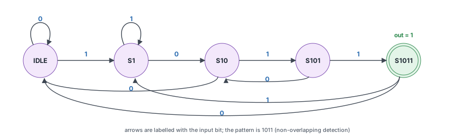
The output is high only in state S1011, so it depends on the state alone. This makes the detector a Moore machine, and the output goes high for one clock cycle, on the clock edge after the last bit of the pattern is received. See Verilog FSM for Moore and Mealy machines.
Quick Check
Q: The FSM is in S101 and receives a 0. Why does it go to S10 and not to IDLE?
Show Answer
The last four bits are "1010", and its ending "10" is the start of "1011". If the next two bits are 1 and 1, the stream ends in "1011" and must be detected. Going to IDLE would lose the "10" and miss that match, for example in the stream 101011.
Example
module det_1011 ( input clk,
                  input rstn,
                  input in,
                  output out );

  // State encoding: 5 states need 3 bits
  localparam IDLE 	= 0,
  			S1 		= 1,
  			S10 	= 2,
  			S101 	= 3,
  			S1011 	= 4;

  reg [2:0] cur_state, next_state;

  // Moore output: high only while the full pattern has been received
  assign out = cur_state == S1011 ? 1 : 0;

  // State register
  always @ (posedge clk) begin
    if (!rstn)
      	cur_state <= IDLE;
     else
     	cur_state <= next_state;
  end

  // Next-state logic
  always @ (cur_state or in) begin
    case (cur_state)
      IDLE : begin
        if (in) next_state = S1;
        else next_state = IDLE;
      end

      S1: begin
        if (in) next_state = S1;      // "11": the last 1 can still start the pattern
        else 	next_state = S10;
      end

      S10 : begin
        if (in) next_state = S101;
        else 	next_state = IDLE;
      end

      S101 : begin
        if (in) next_state = S1011;
        else 	next_state = S10;     // "1010": keep the trailing "10"
      end

      S1011: begin
        if (in) next_state = S1;      // Start a new search with this 1
        else    next_state = IDLE;
      end

      default : next_state = IDLE;    // Codes 5 to 7 are unused
    endcase
  end
endmodule
Synthesis result: The tool builds a 3-bit state register with synchronous reset, next-state logic made of gates and muxes that implement the transition table, and a single gate for out that decodes state 4 (3'b100). With one-hot encoding, the register would use 5 flip-flops and out would be one of them directly.
Where are Sequence Detectors Used?
Serial links mark the start of each frame with a fixed bit pattern, called a sync word or frame delimiter. The receiver runs a detector like this one on the incoming bit stream to find the pattern and align itself to the frame boundaries before decoding the data that follows.
Testbench
The testbench uses a 20 ns clock period and holds reset for five clock edges. It then drives a directed stream that contains the pattern twice, followed by a loop that applies random values. A $strobe at each rising edge prints in and out after all updates for that edge have been made.
module tb;
  reg 			clk, in, rstn;
  wire 			out;
  reg [1:0] l_dly;
  reg 			tb_in;
  integer 	i;
  integer 	loop = 1;

  always #10 clk = ~clk;

  det_1011 u0 ( .clk(clk), .rstn(rstn), .in(in), .out(out) );

  // Print the values at the end of each rising-edge time step
  always @ (posedge clk)
    $strobe ("T=%0t in=%0b out=%0b", $time, in, out);

  initial begin
  	clk <= 0;
    rstn <= 0;
    in <= 0;

    repeat (5) @ (posedge clk);
    rstn <= 1;

		// Generate a directed pattern
    @(posedge clk) in <= 1;
    @(posedge clk) in <= 0;
    @(posedge clk) in <= 1;
    @(posedge clk) in <= 1; 		// Pattern is completed
    @(posedge clk) in <= 0;
    @(posedge clk) in <= 0;
    @(posedge clk) in <= 1;
    @(posedge clk) in <= 1;
    @(posedge clk) in <= 0;
    @(posedge clk) in <= 1;
    @(posedge clk) in <= 1; 	 // Pattern completed again

    // Or random stimulus using a for loop that drives a random
    // value of input N times
    for (i = 0 ; i < loop; i = i + 1) begin
      l_dly = $random;
      repeat (l_dly) @ (posedge clk);
      tb_in = $random;
      in <= tb_in;
    end

    // Wait for sometime before quitting simulation
    #100 $finish;
  end
endmodule
ncsim> run
T=10 in=0 out=0
T=30 in=0 out=0
T=50 in=0 out=0
T=70 in=0 out=0
T=90 in=0 out=0
T=110 in=1 out=0
T=130 in=0 out=0
T=150 in=1 out=0
T=170 in=1 out=0
T=190 in=0 out=1
T=210 in=0 out=0
T=230 in=1 out=0
T=250 in=1 out=0
T=270 in=0 out=0
T=290 in=1 out=0
T=310 in=1 out=0
T=330 in=1 out=1
T=350 in=1 out=0
T=370 in=1 out=0
T=390 in=1 out=0
Simulation complete via $finish(1) at time 410 NS + 0
Each line shows the bit that was just driven onto in and the output after the state register updated. A bit driven at one edge is sampled by the FSM at the next edge, so out rises one clock after the last bit of the pattern appears:
- The bits 1, 0, 1, 1 are driven at 110 to 170 ns, and
outis 1 at 190 ns. - The second stream, 0, 0, 1, 1, 0, 1, 1 at 190 to 310 ns, contains "1011" at its end. The "11" at 230 and 250 ns does not reset the search, because S1 stays in S1 on a 1.
outis 1 again at 330 ns.
Overlapping vs Non-Overlapping Detection
When two occurrences of the pattern share bits, the detector must be told whether to count both. In the stream 1011011, the pattern appears at bits 1 to 4 and again at bits 4 to 7, sharing the middle 1.
- A non-overlapping detector, like
det_1011, starts a fresh search after each match. It detects only the first occurrence in1011011. - An overlapping detector keeps the useful ending of a completed match. From S1011, a 0 leaves "10" as the ending, so it goes to S10 instead of IDLE. It detects both occurrences in
1011011.
// Overlapping version: only the S1011 transitions change
S1011: begin
  if (in) next_state = S1;    // "...1011" + "1": ending "1"
  else    next_state = S10;   // "...1011" + "0": ending "10"
end
Which one is correct depends on the specification. Frame delimiters in a data stream usually need non-overlapping detection, while monitoring logic that counts every occurrence of an event pattern needs overlapping detection.
Protocol Violation Monitors
Verification environments and on-chip debug logic watch control signals for illegal sequences, such as two consecutive write commands without an acknowledge in between. Each check is a small sequence detector whose output raises an error flag or triggers a debug capture when the forbidden pattern appears.
Quick Check
Q: How many times does each version detect the pattern in the stream 1011011011?
Show Answer
The overlapping version detects it 3 times, at bits 1-4, 4-7 and 7-10. The non-overlapping version detects it at bits 1-4, then starts a fresh search at bit 5, which skips the shared 1. It finds the next complete "1011" at bits 7-10, for 2 detections in total.
Wake-Up Patterns
Low-power receivers in wireless sensors and key fobs keep only a small detector running while the rest of the chip sleeps. When it recognizes a specific wake-up bit pattern on the incoming signal, it turns on the main receiver, so the device spends almost no power while waiting.
Common Beginner Mistakes
Mistake #1: Returning to IDLE on every mismatch
Wrong: S1: if (in) next_state = IDLE; or S101: else next_state = IDLE;
Right: Go to the state for the longest ending of the received bits that starts the pattern: S1 for "11", S10 for "1010"
Why? Going to IDLE throws away bits that could be the start of the next match. With S1 going to IDLE on a 1, the stream 11011 is never detected, because the second 1 is discarded. Check every mismatch transition against the reasoning column of the transition table.
Mistake #2: No default in the next-state case
Wrong: A case with only the five state items, for a 3-bit state register
Right: Add default: next_state = IDLE;
Why? A 3-bit register has 8 codes and only 5 are used. For the other 3, no item assigns next_state, so synthesis infers a latch on it. If the register ever reaches an unused code, the FSM also has no defined way back to IDLE.
Mistake #3: Expecting out on the same edge as the last bit
Wrong: Checking out in the testbench on the same clock edge that drives the final 1 of the pattern
Right: Check out one clock edge after the final bit is driven
Why? A bit driven onto in at an edge is sampled by the state register at the next edge, and this Moore output follows the state register. The log shows this: the last bit is driven at 170 ns and out is 1 at 190 ns. A Mealy version, with out = (cur_state == S101) & in, responds one cycle earlier.
Mistake #4: Confusing overlapping and non-overlapping behavior
Wrong: Writing S1011 ? IDLE on a 0 when the specification counts every occurrence
Right: Decide from the specification, then write the S1011 transitions to match
Why? Both versions detect isolated patterns identically, so a testbench that never sends overlapping patterns cannot tell them apart. Always include an overlapping case, such as 1011011, in the test stimulus.
Practice Exercise
Challenge: Overlapping 110 Detector
Write a Moore FSM det_110 that detects the pattern 110, with overlapping detection, using the same port list as det_1011. List the states and the transition table first, then write the code.
Hint
The states are IDLE, S1, S11 and S110. In S11, another 1 still leaves "11" at the end of the stream. After a match, the stream ends in "0", which is not a start of "110".
Solution
module det_110 ( input clk,
                 input rstn,
                 input in,
                 output out );

  localparam IDLE = 2'd0,
             S1   = 2'd1,
             S11  = 2'd2,
             S110 = 2'd3;

  reg [1:0] cur_state, next_state;

  assign out = (cur_state == S110);

  always @(posedge clk) begin
    if (!rstn) cur_state <= IDLE;
    else       cur_state <= next_state;
  end

  always @(*) begin
    case (cur_state)
      IDLE : next_state = in ? S1  : IDLE;
      S1   : next_state = in ? S11 : IDLE;
      S11  : next_state = in ? S11 : S110;   // "111" still ends in "11"
      S110 : next_state = in ? S1  : IDLE;   // "1101" ends in "1"; "1100" in nothing
      default : next_state = IDLE;
    endcase
  end

endmodule
For "110", the overlapping and non-overlapping versions behave the same: a completed match ends in "0", which never starts the pattern, so no bits can be shared. With exactly 4 states, the 2-bit state register has no unused codes. The default item is kept anyway, so the case stays complete if states are added later.
Summary
In this tutorial, you learned:
- A sequence detector is an FSM whose states record how much of the pattern has been matched
- On a mismatch, the FSM must go to the state for the longest ending that still starts the pattern, not always to IDLE
- A Moore detector raises its output one clock after the last bit of the pattern is sampled
- Non-overlapping detectors start fresh after a match; overlapping detectors keep the shared bits
- Unused state codes need a
defaultin the next-statecase - Test stimulus must include near-misses and overlapping patterns, not just isolated matches
