
What You'll Learn
- Master continuous assignments with
assignfor modeling combinational logic - Understand the critical difference between
wire(continuous) andreg(procedural) assignments - Apply concatenation, part-select, and replication operators in assign statements
- Recognize multiple driver conflicts and high-impedance (Z) states from undriven nets
Signals of type wire or a similar wire like data type requires the continuous assignment of a value. For example, consider an electrical wire used to connect pieces on a breadboard. As long as the +5V battery is applied to one end of the wire, the component connected to the other end of the wire will get the required voltage.

In Verilog, this concept is realized by the assign statement where any wire or other similar wire like data-types can be driven continuously with a value. The value can either be a constant or an expression comprising of a group of signals.
Assign Syntax
The assignment syntax starts with the keyword assign followed by the signal name which can be either a single signal or a concatenation of different signal nets. The drive strength and delay are optional and are mostly used for dataflow modeling than synthesizing into real hardware. The expression or signal on the right hand side is evaluated and assigned to the net or expression of nets on the left hand side.
assign <net_expression> = [drive_strength] [delay] <expression of different signals or constant value>
Delay values are useful for specifying delays for gates and are used to model timing behavior in real hardware because the value dictates when the net should be assigned with the evaluated value.
Rules
There are some rules that need to be followed when using an assign statement:
- LHS should always be a scalar or vector net or a concatenation of scalar or vector nets and never a scalar or vector register.
- RHS can contain scalar or vector registers and function calls.
- Whenever any operand on the RHS changes in value, LHS will be updated with the new value.
assignstatements are also called continuous assignments and are always active
Example #1
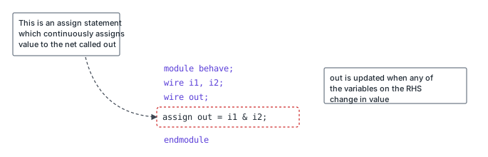
In the following example, a net called out is driven continuously by an expression of signals. i1 and i2 with the logical AND & form the expression.
If the wires are instead converted into ports and synthesized, we will get an RTL schematic like the one shown below after synthesis.

Continuous assignment statement can be used to represent combinational gates in Verilog.
Example #2
The module shown below takes two inputs and uses an assign statement to drive the output z using part-select and multiple bit concatenations. Treat each case as the only code in the module, else many assign statements on the same signal will definitely make the output become X.
module xyz (input [3:0] 	x,		// x is a 4-bit vector net
						input 				y, 		// y is a scalar net (1-bit)
						output [4:0] 	z ); 	// z is a 5-bit vector net (output)

wire [1:0] 	a;  // Internal 2-bit wire
wire 				b;  // Internal 1-bit wire

// ========== DEMONSTRATION OF ASSIGN FEATURES ==========
// Test case: Assume x=4'hC (4'b1100) and y=1'b1
// NOTE: Only ONE case should be active in real design!

// ===== Case #1: Full Concatenation =====
// Concatenation {x, y} combines 4-bit x and 1-bit y -> 5-bit result
// Result: z = {4'b1100, 1'b1} = 5'b11001 = 5'h19
assign z = {x, y};

// ===== Case #2: Partial Assignment (creates high-impedance) =====
// Only z[3:1] is driven, z[4] and z[0] are undriven -> high-impedance (Z)
// z[3:1] gets the lowest 3 bits of {x, y} = {x[1:0], y} = 3'b001
// Result: z = 5'bZ001Z (bit 4 and bit 0 are undriven)
assign z[3:1] = {x, y};

// ===== Case #3: Multiple Assign on Different Bits =====
// z[3:1] assigned from concatenation, z[4] driven separately
// Now only z[0] remains undriven
// Result: z = 5'b1001Z (bit 0 still undriven)
assign z[3:1] = {x, y};
assign z[4] = 1;

// ===== Case #4: Multiple Drivers, Same Value (No Conflict) =====
// z[3] is driven TWICE: First from z[3:1], second from explicit assign
// Both drive bit3 with same value (0), so no contention
// z[3] gets 0 from the concatenation, and the explicit assign z[3]=0 adds a second driver
// Result: z = 5'bZ001Z (bit 3 has two drivers with same value)
assign z[3:1] = {x, y};
assign z[3] = 0;

// ===== Case #5: Multiple Drivers, Different Values (CONFLICT!) =====
// z[3] is driven with DIFFERENT values: 0 (from the concatenation) vs 1 (explicit assign)
// Creates driver conflict -> result is X (unknown)
// Result: z = 5'bZX01Z (bit 3 is X due to conflicting drivers)
assign z[3:1] = {x, y};
assign z[3] = 1;

// ===== Case #6: Part-Select on RHS =====
// Only x[1:0] used (not full x), concatenated with y
// {x[1:0], y} = {2'b00, 1'b1} = 3'b001
// z is 5-bit, so padded with zeros: z = 5'b00001
assign z = {x[1:0], y};

// ===== Case #7: Partial LHS Assignment =====
// Only z[2:0] driven, z[4:3] undriven -> high-impedance
// z[2:0] = {x[1:0], y} = 3'b001
// Result: z = 5'bZZ001
assign z[2:0] = {x[1:0], y};

// ===== Case #8: Replication Operator =====
// {3{y}} replicates y three times: {y, y, y}
// Result: z = {1'b1, 1'b1, 1'b1} = 5'b00111 (padded to 5 bits)
assign z = {3{y}};

// ===== Case #9: Concatenated LHS =====
// LHS {a, b} is 3-bit (2+1), RHS {x, y} is 5-bit
// Only rightmost 3 bits of RHS assigned to LHS
// {x, y} = 5'b11001, LSB 3 bits = 3'b001
// a gets upper 2 bits (00), b gets lower 1 bit (1)
// Result: a = 2'b00, b = 1'b1
assign {a, b} = {x, y};

// ===== Case #10: Reversed LHS Order =====
// Same as Case #9 but LHS order reversed: {b, a}
// {x, y} = 5'b11001, LSB 3 bits = 3'b001
// b gets upper 1 bit (0), a gets lower 2 bits (01)
// Result: a = 2'b01, b = 1'b0
assign {b, a} = {x, y};

endmodule
Assign reg variables
It is illegal to drive or assign reg type variables with an assign statement. This is because a reg variable is capable of storing data and does not require to be driven continuously. reg signals can only be driven in procedural blocks like initial and always.
Implicit Continuous Assignment
When an assign statement is used to assign the given net with some value, it is called explicit assignment. Verilog also allows an assignment to be done when the net is declared and is called implicit assignment.
wire [1:0] a;
assign a = x & y; 			// Explicit assignment

wire [1:0] a = x & y; 	// Implicit assignment
Combinational Logic Design
Consider the following digital circuit made from combinational gates and the corresponding Verilog code.
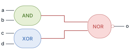
Combinational logic requires the inputs to be continuously driven to maintain the output unlike sequential elements like flip flops where the value is captured and stored at the edge of a clock. So an assign statement fits the purpose well because the output o is updated whenever any of the inputs on the right hand side change.
// This module takes four inputs and performs a boolean
// operation and assigns output to o. The combinational
// logic is realized using assign statement.

module combo (	input 	a, b, c, d,  // Four input signals
								output o);         // Output signal (must be wire type)

 // Continuous assignment: o is ALWAYS driven by this expression
 // Whenever a, b, c, or d changes, o is immediately updated
 // Expression breakdown: NOT((a AND b) OR (c XOR d))
 assign o = ~((a & b) | (c ^ d));

endmodule
Hardware Schematic
After design elaboration and synthesis, we do get to see a combinational circuit that would behave the same way as modeled by the assign statement.

See that the signal o becomes 1 whenever the combinational expression on the RHS becomes true. Similarly o becomes 0 when RHS is false. Output o is X from 0ns to 10ns because inputs are X during the same time.

| Feature | assign (Continuous) | always (Procedural) |
|---|---|---|
| Signal Type | Must be wire or net type | Must be reg or variable type |
| Execution | Continuous (always active) | Triggered by sensitivity list or event |
| Assignment Type | No operator (just =) | Blocking (=) or nonblocking (<=) |
| Hardware Inference | Combinational logic (gates) | Combinational or sequential logic |
| Multiple Assignments | Creates driver conflict (X or Z) | Last assignment wins (sequential execution) |
| Use Case | Simple combinational logic, wire connections | Complex logic, state machines, flip-flops |
Real-World Application: Bus Multiplexing in SoC Interconnects
In System-on-Chip (SoC) designs, address and data buses from multiple masters (CPU, DMA, GPU) connect to shared peripherals through multiplexers implemented with assign statements. A typical AXI/AHB bus arbiter uses:
assign data_bus = (sel == 2'b00) ? cpu_data : (sel == 2'b01) ? dma_data : (sel == 2'b10) ? gpu_data : 32'hZ;
This continuous assignment ensures zero-delay bus switching when arbitration changes, critical for high-bandwidth communication. The high-impedance (Z) state for unused case prevents bus contention when no master is selected.
Real-World Application: Combinational Datapath in ALUs
Arithmetic Logic Units (ALUs) in processors use assign statements for combinational datapaths like adders, shifters, and logic operations. For example, a 32-bit ALU might implement:
assign result = (op == ADD) ? a + b : (op == SUB) ? a - b : (op == AND) ? a & b : (op == OR) ? a | b : 32'h0;
This creates a pure combinational circuit with nanosecond-scale propagation delay, enabling single-cycle execution of arithmetic instructions. Modern RISC-V and ARM processors rely heavily on these assign-based datapaths for high-frequency operation (3+ GHz).
Common Beginner Mistakes
Mistake #1: Using assign with reg Variables
module bad_design (
  input a, b,
  output reg out  // Declared as reg
);

assign out = a & b;  // ERROR: Cannot use assign on reg type
endmodule

// Compiler error: "left-hand side of continuous assign must be net"
Why it's problematic: assign statements can only drive wire (net) types, not reg (variable) types. The reg keyword indicates procedural assignment (from always, initial, task, function), while assign requires continuous assignment. Mixing these causes compilation errors. This is a fundamental type mismatch in Verilog's type system.
Best Practice: If using assign, declare outputs as output wire (or just output, which defaults to wire). If using always blocks, declare as output reg. Correct:
module good_design (input a, b, output out);
  assign out = a & b;
endmodule
See our guide on Verilog Data Types
Mistake #2: Creating Unintentional High-Impedance (Z) States
module partial_assign (
  input [3:0] data,
  output [7:0] result
);

assign result[3:0] = data;  // Only drives lower 4 bits
// result[7:4] is UNDRIVEN -> becomes Z (high-impedance)
endmodule

// Testbench simulation shows: result = 8'bZZZZ1010 (unexpected Zs!)
Why it's problematic: Partially assigning a vector leaves undriven bits in high-impedance (Z) state. In testbenches, Z propagates through logic creating X (unknown) values, breaking assertions and comparisons. In synthesized hardware, Z states can cause floating inputs to gates or nets to be optimized away, leading to unpredictable behavior, increased power consumption, or latch-up conditions. Most FPGA/ASIC tools issue warnings for undriven nets.
Best Practice: Always drive all bits of an output. Use concatenation to specify all bits: assign result = {4'b0000, data}; or multiple assigns covering all bits. Check synthesis warnings for undriven nets. For intentional tri-state buses, explicitly assign Z when needed.
Mistake #3: Multiple assign Statements Creating Driver Conflicts
module conflict (
  input a, b, c,
  output out
);

assign out = a & b;  // First driver
assign out = b | c;  // Second driver - CONFLICT!

// Simulation result: out = X (unknown) due to multiple drivers
endmodule
Why it's problematic: Multiple assign statements driving the same net create multiple drivers, resulting in unknown (X) values when drivers provide different outputs. Unlike procedural assignments (where last assignment wins), continuous assignments are concurrent and all active simultaneously. This models real hardware wire conflicts where multiple gates drive the same line, causing contention and unpredictable voltage levels.
Best Practice: Use only ONE assign per net. For conditional logic, use ternary operators or combine expressions: assign out = sel ? (a & b) : (b | c);. For complex muxing, use always @(*) blocks instead. Synthesis tools reject multiple drivers or insert tri-state buffers, often not the intended behavior.
Mistake #4: Confusing Concatenation Order (MSB vs LSB)
reg [3:0] upper = 4'hA;  // 4'b1010
reg [3:0] lower = 4'h5;  // 4'b0101
wire [7:0] result;

assign result = {lower, upper};  // WRONG: Expects {upper, lower}
// User expects: result = 8'hA5 (1010_0101)
// Actual result: result = 8'h5A (0101_1010) - reversed!
Why it's problematic: Concatenation {a, b} places a in the most significant bits (MSB) and b in least significant bits (LSB). Beginners often assume left-to-right order matches bit significance, but it's the opposite of intuition for those thinking in decimal/hex notation. This creates subtle bugs in byte swapping, endianness conversion, and bit field packing where values are reversed from expected.
Best Practice: Remember concatenation order: {MSB, ... , LSB}. The leftmost element becomes the highest bits. Correct: assign result = {upper, lower}; yields 8'hA5. Use explicit bit indexing to verify: result[7:4] = upper, result[3:0] = lower. See our tutorial on Concatenation.
Summary
In this tutorial, you learned:
assignstatements provide continuous assignment towirenets, modeling combinational logic with zero procedural delay- Continuous assignments differ fundamentally from procedural assignments: wire vs reg, concurrent vs sequential, always-active vs event-triggered
- Concatenation (
{a,b}), part-select ([3:0]), and replication ({3{a}}) enable flexible bit manipulation in assign statements - Multiple drivers on the same net create conflicts (X values); undriven nets default to high-impedance (Z), both causing simulation and synthesis issues
- Assign statements synthesize to combinational gates (AND, OR, MUX), making them ideal for datapaths, multiplexers, and simple Boolean logic
