
When a signal passes from logic driven by one clock to logic driven by a different, unrelated clock, it crosses a clock domain boundary. The receiving flip-flop has no fixed timing relationship with the signal, so setup and hold cannot be guaranteed and the flip-flop can go metastable. Clock domain crossing (CDC) design uses synchronizers to make metastability harmless for single bits, and Gray code, handshakes, or asynchronous FIFOs to move multi-bit data safely.
15 min read | Intermediate Level
What You'll Learn
- Why signals crossing clock domains cause metastability, and how a two-flop synchronizer handles it
- How synchronizer reliability (MTBF) grows with resolution time
- Why multi-bit values cannot be synchronized bit by bit, and what to use instead
- How pulse synchronizers, Gray-code pointers, and reset synchronizers are structured
Why Crossings Are Dangerous
Within one clock domain, static timing analysis guarantees that data is stable around every capturing edge. Across unrelated clocks, the data can change at any moment relative to the receiving clock, including right inside its setup-hold window. Sooner or later it will, and when it does, the flip-flop may hover between 0 and 1 for an unpredictable time before settling.
What happens at an unsynchronized crossing

  data changes inside the capture window
    -> flip-flop output goes metastable (neither 0 nor 1)
    -> it eventually settles to 0 or 1, but the time is unbounded
    -> logic downstream may see different values in different places
    -> the design misbehaves intermittently, often only in silicon
The Two-Flop Synchronizer
The standard fix for a single bit is to pass it through two flip-flops in the receiving domain before any logic uses it. The first flop may go metastable, but it has a whole receiving-clock cycle to settle before the second flop samples it.
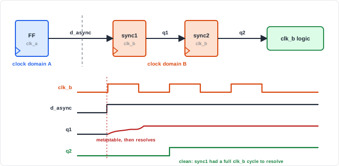
Two-flop synchronizer (clk_dst is the receiving clock)

  d_async --> [FF1] --> [FF2] --> q_sync
  (from a flip-flop    ^       ^
   in the source       clk_dst clk_dst
   domain)

  FF1 may go metastable; FF2 samples it a full clk_dst cycle later
  2 stages is typical; 3 stages for very high clock rates
The two flops are plain flip-flops in a chain, with no logic between them. They must be placed close together and must not be optimized, retimed, or duplicated; flows mark them with tool-specific attributes, and some libraries provide dedicated synchronizer cells with faster resolution. The input must come directly from a flip-flop in the source domain.
How reliable is it?
Metastability cannot be eliminated, only made extremely unlikely. The mean time between failures (MTBF) of a synchronizer grows exponentially with the time the first flop is given to resolve.
Synchronizer MTBF in proportions

  MTBF  proportional to  e^(resolution time / tau)  /  (clock frequency x data change rate)

  tau: a flip-flop constant, set by the process (tens of picoseconds or less)

  resolution time + 1 tau     ->  MTBF x 2.7
  resolution time + 10 tau    ->  MTBF x 22,000
  add a third flop            ->  one more full clock period of resolution time
  faster clock, faster data   ->  more chances to fail, lower MTBF
At moderate clock rates, two flops typically give an MTBF of many years or more. At very high clock rates, where a cycle leaves little resolution time, designs use three flops.
Quick Check
Q: Why must the signal come directly from a flip-flop in the source domain, not from combinational logic?
Show Answer
Combinational logic can glitch as its inputs change. In the source domain those glitches are harmless because they settle before the next source edge, but the destination clock is unrelated and can sample a glitch as a real pulse. Registering the signal in its own domain first guarantees a clean, glitch-free level.
Multi-Bit Values: Why Bit-by-Bit Fails
If each bit of a bus is synchronized separately, each bit resolves independently. When the bus changes from 0111 to 1000, the receiver might see any mix of old and new bits - 1111, 0000, 1011 - for a cycle. No amount of synchronization fixes that, because the problem is coherence, not metastability.
| What is crossing | Safe technique | Why it works |
|---|---|---|
| A single level signal | Two-flop synchronizer | Only one bit can be uncertain |
| A single-cycle pulse | Toggle (pulse) synchronizer | Converts the pulse to a level change, which cannot be missed |
| A counter or pointer that steps by 1 | Gray code, then synchronize each bit | Only one bit changes per step, so the result is old or new, never garbage |
| A data word that changes occasionally | Request/acknowledge handshake | Data is held stable until the receiver has safely captured it |
| A stream of data | Asynchronous FIFO | Data sits in RAM; only Gray-coded pointers cross |
Pulse synchronizer
A one-cycle pulse from a fast domain can fall entirely between two edges of a slow clock and be missed. Converting it into a toggle solves this:
Toggle (pulse) synchronizer

  Source domain:       a toggle flip-flop flips once per source pulse
  Crossing:            the toggle level goes through a 2-flop synchronizer
  Destination domain:  an XOR of the last two synchronized samples
                       gives one pulse for each change of level

  source pulse  ->  level flips (0->1 or 1->0)  ->  synchronized level
  destination pulse = (new sample) XOR (previous sample)
Source pulses must be spaced far enough apart - typically at least two or three destination clock cycles - or two toggles can cancel before the receiver sees them. Faster, back-to-back events need a handshake or FIFO.
Gray-code pointers and the asynchronous FIFO
In Gray code, consecutive values differ in exactly one bit. If a Gray-coded pointer is sampled while changing, the uncertain bit makes the result either the old value or the new value - both valid.
Binary <-> Gray conversion for an N-bit pointer (b = binary, g = Gray)

  binary -> Gray :  g(N-1) = b(N-1)          g(i) = b(i+1) XOR b(i)
  Gray -> binary :  b(N-1) = g(N-1)          b(i) = b(i+1) XOR g(i)   (running XOR from the MSB)
| Binary | Gray |
|---|---|
| 000 | 000 |
| 001 | 001 |
| 010 | 011 |
| 011 | 010 |
| 100 | 110 |
| 101 | 111 |
| 110 | 101 |
| 111 | 100 |
Between every pair of consecutive rows, and also from the last row back to the first, exactly one bit changes (see Gray Code). That is the property an asynchronous FIFO pointer needs.
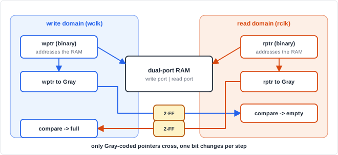
An asynchronous FIFO keeps its data in a dual-port RAM written in one domain and read in the other. The write pointer is converted to Gray code, registered, and synchronized into the read domain to compute empty; the read pointer crosses the other way to compute full. Because a synchronized pointer may lag by a cycle or two, the FIFO sometimes reports full or empty slightly early - always the safe direction.
Reset synchronizer
Reset synchronizer: asynchronous assert, synchronous de-assert

  rst_async_n --(async clear)--> [FF1] --> [FF2] --> rst_sync_n
  constant 1 ---------------------> D of FF1       both flops clocked by clk

  assert  : rst_async_n goes low -> both flops clear at once, no clock needed
  release : rst_async_n goes high -> the 1 shifts through two flops,
            so rst_sync_n rises two clock edges later, in step with clk
Releasing a reset asynchronously can leave some flip-flops out of reset one cycle before others, or make them metastable. Synchronizing the release keeps every flop in the domain leaving reset on the same edge.
Where Does CDC Matter?
A modern SoC has many clock domains: CPU clusters, memory controllers, peripheral buses, and interface blocks for USB, PCIe, and display, each with its own clock. Every connection between them is a crossing. CDC bugs are notoriously hard to find in simulation because they depend on exact clock phases, and they are a well-known cause of silicon failures, so teams run structural CDC analysis tools that check every crossing for proper synchronization before tape-out.
Where Are Asynchronous FIFOs Used?
Network interfaces receive data on a clock recovered from the incoming link and pass it to the core clock through an asynchronous FIFO. Video pipelines move pixels from a processing clock to a display clock the same way, and bus bridges between subsystems running at different frequencies use FIFOs in both directions.
Common Mistakes
Mistake #1: Putting combinational logic before the synchronizer
Glitches from logic in the source domain can be captured by the destination clock as real pulses. Always register the signal in the source domain and feed the synchronizer directly from that flop.
Mistake #2: Synchronizing a bus one bit at a time
Each bit resolves independently, so the receiver can see a mix of old and new bits that was never a valid value. Use Gray code for pointers, a handshake for occasional words, or a FIFO for streams.
Mistake #3: Passing a short pulse from a fast domain to a slow one
A one-cycle pulse can occur entirely between two slow-clock edges and vanish. Convert it to a toggle, or stretch it and use a handshake so the receiver acknowledges it.
Mistake #4: Letting separately synchronized signals reconverge
Two related signals synchronized through separate synchronizers can arrive one cycle apart. Logic that combines them may see an impossible combination for a cycle. Synchronize one control signal and derive the others from it, or use a handshake that carries them together.
Practice Exercise
Challenge: Pick the Right Crossing
For each crossing, choose a technique and justify it:
- A
link_upstatus bit that changes rarely and stays at its level for a long time. - A one-cycle
frame_donepulse from a 500 MHz domain to a 100 MHz domain, at most once per microsecond. - A 16-bit configuration register written by software about once per second and read by another domain.
- A continuous stream of 32-bit samples from an ADC clock domain into the processing clock domain.
Hint
Ask: is it one bit or many? A level or a pulse? Occasional or continuous?
Solution
1. link_up: two-flop synchronizer. A single, slow-changing level.

2. frame_done: pulse (toggle) synchronizer. A 2 ns pulse would be missed
   by a 10 ns clock; the toggle turns it into a level change. One pulse
   per microsecond is far slower than the ~2-3 destination cycles needed.

3. Config register: request/acknowledge handshake. Hold the 16 bits
   stable, synchronize a single "valid" or toggle signal, and capture
   the bus in the destination domain once the request is seen.

4. Sample stream: asynchronous FIFO with Gray-coded pointers. It is the
   only option that keeps up with continuous data.
Summary
In this tutorial, you learned:
- Signals crossing between unrelated clocks can violate setup and hold and cause metastability
- A two-flop synchronizer gives a metastable flop a full cycle to resolve before its output is used
- Synchronizer MTBF grows exponentially with resolution time; a third flop adds a full cycle
- Multi-bit values must not be synchronized bit by bit: use Gray code, a handshake, or an asynchronous FIFO
- Pulses from a fast domain are converted to toggles so they cannot be missed
- Resets should be asserted asynchronously and released synchronously in each domain
- CDC problems rarely show up in simulation, so structural CDC analysis is part of sign-off