
The clock must reach every flip-flop in a design at nearly the same moment. The difference in clock arrival time between two flip-flops is called clock skew. Skew changes how much time data has to travel between them: it can help setup timing on one path while breaking hold timing on the same path. Clock tree synthesis (CTS) is the implementation step that builds a buffered clock network with small, controlled skew.
13 min read | Intermediate Level
What You'll Learn
- What clock latency, skew, and uncertainty mean
- How positive and negative skew affect setup and hold timing
- How balanced structures such as the H-tree keep skew small
- How clocking choices (gated and divided clocks) affect clock tree synthesis and timing constraints
Latency, Skew, and Uncertainty
The clock is the largest and busiest net on a chip: it can reach millions of flip-flops and toggles every cycle. It cannot be one wire from one driver, so it is distributed through a tree of buffers. Three terms describe how well that works:
| Term | Meaning | Why it matters |
|---|---|---|
| Latency (insertion delay) | Time from the clock source to a flip-flop's clock pin | Large latency is fine if it is equal everywhere; it matters at interfaces with other clocks |
| Skew | Difference in latency between two flip-flops | Directly shifts the timing window of every path between them |
| Uncertainty (jitter) | Cycle-to-cycle variation in edge timing, from the clock source and supply noise | Reduces the usable clock period; modelled as a margin in timing analysis |
How Skew Changes Setup and Hold
For a path from a launching flip-flop (FF1) to a capturing flip-flop (FF2), define skew as the capture clock's arrival time minus the launch clock's arrival time. Positive skew means the capture clock arrives later.
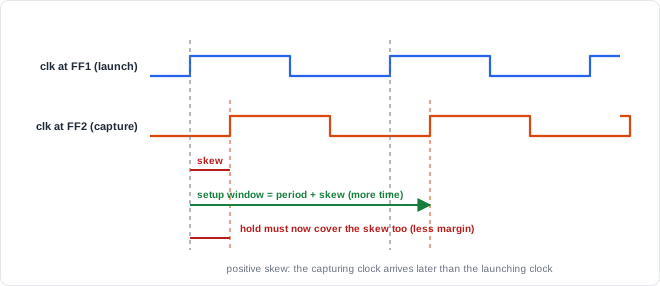
Setup and hold with skew (skew = capture clock arrival - launch clock arrival)

  SETUP:  clock period + skew  >=  clock-to-Q + max logic delay + setup time
          positive skew adds time  -> helps setup
          negative skew removes time -> hurts setup

  HOLD:   clock-to-Q + min logic delay  >=  hold time + skew
          positive skew raises the bar -> hurts hold
          negative skew lowers the bar -> helps hold

  The same skew that helps one check hurts the other.
Hold is the dangerous side. Setup failures can be fixed by lowering the clock frequency, but hold does not depend on the clock period at all. A hold violation caused by skew fails at every frequency and must be fixed by adding delay to the short path or by reducing the skew.
Quick Check
Q: A path has clock-to-Q = 50 ps, minimum logic delay = 30 ps, and hold time = 20 ps. How much positive skew can it tolerate before failing hold?
Show Answer
Hold requires 50 + 30 ≥ 20 + skew, so skew must be at most 60 ps. Any more positive skew than 60 ps causes a hold violation, whatever the clock frequency.
Building a Low-Skew Clock Network
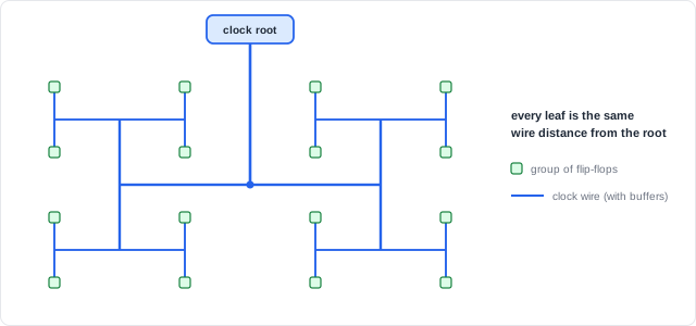
The classic way to equalize latency is a symmetric structure. In an H-tree, the clock splits into two equal branches, each of which splits again, so every endpoint is the same wire distance from the root:
Real chips do not have flip-flops on a perfect grid, so clock tree synthesis builds a buffered tree tailored to where the flip-flops were placed:
Clock tree synthesis (simplified)

  1. Collect all clock sinks (flip-flop and memory clock pins) after placement
  2. Cluster nearby sinks and give each cluster a buffer
  3. Build upward: cluster the buffers, add another level, repeat to the root
  4. Balance: adjust buffer sizes and wire routes so latencies match
  5. Route clock nets with special rules (wider spacing, shielding, upper metal)
  6. Report latency, skew, and transition time; iterate if targets are missed
Where Are Clock Structures Pushed Hardest?
High-frequency processors often use a clock mesh - a grid of shorted clock wires driven from many points - or a spine-and-tree hybrid. The mesh averages out differences between drivers and gives very low skew, at the cost of extra power. Lower-frequency, power-sensitive designs use plain buffered trees, which are cheaper in power. In both cases the clock network is one of the largest consumers of dynamic power on the chip.
Useful Skew
Because skew moves time from one side of a flip-flop to the other, tools can apply it on purpose. If a path into a flip-flop is failing setup and the path out of it has slack, delaying that flip-flop's clock slightly borrows time from the next stage. This useful skew is applied during implementation, and it must still satisfy hold on every affected path.
What the Designer Controls
CTS works best when every flip-flop sits on a clean, directly driven clock. A design that generates or gates clocks with ordinary logic makes the clock tree harder to balance and can introduce glitches:
Avoid: clock gated with plain logic, and a divided clock from a flip-flop
    gated clock = CLK AND EN       -> glitches if EN changes while CLK is high
    divided clock = flip-flop toggling every CLK edge, clocking other flip-flops
                                   -> a new clock domain the tree must handle

Prefer: keep one clock and use enables
    EN_DIV2 toggles every cycle (high every other cycle)
    the slow flip-flops load only when EN_DIV2 is high
                                   -> same effect, no new clock
The enable style gives ordinary flip-flops with enable multiplexers, or integrated clock-gating cells if clock gating is enabled - both safe for CTS. When a divided or gated clock is genuinely needed, it is built with dedicated clock-gating or divider cells and declared in the timing constraints, so that timing analysis knows the relationship:
| Constraint | What it tells the timing tools |
|---|---|
| Clock definition | The clock's source point and period (for example a 1 ns period, which is 1 GHz) |
| Clock uncertainty | A margin for jitter and supply noise (for example 50 ps) that shortens the usable period |
| Generated clock | A divided or gated clock, with its source clock and divide ratio, so its relationship to the main clock is known |
Where Does Clock Skew Cause Real Problems?
Hold violations after CTS are a routine part of implementation: once real clock latencies replace ideal clocks, short paths between flip-flops with different latencies often fail hold, and tools insert delay buffers to fix them. Interfaces between blocks with separately built clock trees, and paths to hard macros such as memories, need particular care because their latencies are balanced independently.
Common Mistakes
Mistake #1: Assuming skew is always bad
Skew moves time between setup and hold. Positive skew helps setup and hurts hold; negative skew does the opposite. Implementation tools even use skew deliberately. What matters is that every path still meets both checks.
Mistake #2: Trying to fix hold violations by slowing the clock
Hold checks compare two paths launched and captured by the same clock edge, so the clock period cancels out. A skew-induced hold violation fails at every frequency and needs delay added to the short path.
Mistake #3: Gating or dividing clocks with ordinary logic
An AND gate on the clock can glitch and creates a clock that CTS cannot balance cleanly with the rest of the tree. Use enables, or dedicated clock-gating cells inserted by the tools.
Mistake #4: Leaving generated clocks undeclared
If a divided clock is not declared in the timing constraints, timing analysis does not know its relationship to the source clock, and paths between them may be analysed wrongly or not at all.
Practice Exercise
Challenge: Skew in Both Directions
A path has: clock period 1000 ps, clock-to-Q 50 ps, maximum logic delay 850 ps, minimum logic delay 30 ps, setup time 40 ps, hold time 20 ps.
- Compute setup and hold slack with zero skew.
- Repeat with +80 ps skew (capture clock later).
- Repeat with -80 ps skew (capture clock earlier).
Hint
Setup slack = (period + skew) - (clock-to-Q + max logic + setup). Hold slack = (clock-to-Q + min logic) - (hold + skew).
Solution
                 setup slack                     hold slack
  skew =   0:  1000 - (50+850+40) =  60 ps     (50+30) - (20+0)   =  60 ps
  skew = +80:  1080 - 940         = 140 ps     80 - (20+80)       = -20 ps  FAIL
  skew = -80:   920 - 940         = -20 ps FAIL 80 - (20-80)      = 140 ps

  +80 ps fixes nothing: it creates a hold failure that no clock
  frequency can fix. -80 ps creates a setup failure instead.
Summary
In this tutorial, you learned:
- Clock latency is the delay to each flip-flop; skew is the difference in latency between two flip-flops
- Positive skew helps setup and hurts hold; negative skew does the opposite
- Hold violations from skew fail at every frequency and are fixed by adding delay or reducing skew
- Symmetric structures such as the H-tree equalize latency; CTS builds balanced buffered trees for real placements
- Useful skew deliberately moves time between pipeline stages
- Designs should use enables instead of logic-gated or flip-flop-divided clocks, and any generated clock must be declared in the constraints