
Two wires running side by side form a capacitor. When one of them switches, some of that change couples onto its neighbour. This crosstalk can put a glitch on a wire that should be quiet, or it can speed up or slow down a wire that is switching at the same time. The switching wire is called the aggressor, and the affected wire is the victim. In dense modern processes, coupling to neighbours is a large share of a wire's capacitance, so crosstalk is checked on every net before sign-off.
12 min read | Intermediate Level
What You'll Learn
- How coupling capacitance between wires creates crosstalk
- The difference between crosstalk noise (glitches) and crosstalk delay
- How the Miller coupling factor changes the effective capacitance of a switching wire
- How spacing, shielding, and driver sizing reduce crosstalk
Aggressor, Victim, and Coupling Capacitance
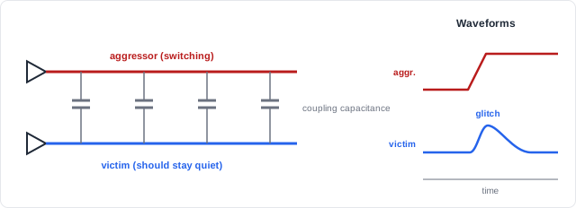
A wire's total capacitance has two parts: capacitance to the substrate and to layers above and below (Cg), and capacitance to its neighbours on the same layer (Cc). As wires get taller and closer together, the neighbour part grows. At tight spacing it can be the majority of a wire's capacitance.
Coupling in proportions

  closer spacing          -> larger coupling capacitance
  longer parallel run     -> larger coupling capacitance
  faster aggressor edge   -> larger glitch
  weaker victim driver    -> larger glitch (less able to hold the victim steady)
  more coupling fraction  -> larger glitch and larger delay change
Effect 1: Crosstalk Noise (Glitches)
If the victim is supposed to be steady, the aggressor's edge pushes charge through the coupling capacitance and bumps the victim's voltage. The victim's driver then pulls it back, so the result is a glitch rather than a permanent change.
Worst-case glitch estimate (victim not driven at all)

  glitch = VDD x Cc / (Cc + Cg)

  Example: VDD = 0.8 V, Cc = 20 fF, Cg = 30 fF
           glitch = 0.8 x 20 / 50 = 0.32 V   (40% of VDD)

  A real victim is driven, so its driver fights back: the glitch is
  smaller, and a stronger victim driver makes it smaller still.
Whether the glitch causes a failure depends on where it lands:
- On a data input between clock edges: usually harmless, because the flip-flop samples later.
- Near a clock edge, if it crosses the receiver's threshold: it can be captured as a wrong value.
- On a clock, asynchronous reset, or latch enable: it can act as a false edge or a false reset.
- On a dynamic or low-voltage circuit: it can discharge a node that cannot recover.
Effect 2: Crosstalk Delay
When both wires switch at the same time, the coupling capacitance behaves differently depending on direction. The voltage across the coupling capacitor changes by 0, 1, or 2 times VDD, and the victim's driver has to supply charge to match. This is captured by the Miller coupling factor (MCF):
| Neighbour activity | Voltage change across Cc | MCF | Effective capacitance | Effect on victim |
|---|---|---|---|---|
| Switches in the same direction | 0 | 0 | Cg | Speeds up |
| Stays quiet | VDD | 1 | Cg + Cc | Nominal |
| Switches in the opposite direction | 2 x VDD | 2 | Cg + 2Cc | Slows down |
A slowed victim can cause a setup violation; a sped-up victim can cause a hold violation. Timing analysis that ignores crosstalk can therefore be wrong in both directions.
Quick Check
Q: A victim wire has Cg = 30 fF and Cc = 20 fF. What effective capacitance does its driver see when the neighbour switches the opposite way, and how does that compare with a quiet neighbour?
Show Answer
Opposite switching: 30 + 2 x 20 = 70 fF. Quiet neighbour: 30 + 20 = 50 fF. The driver sees 40% more capacitance, so the victim's wire-dominated delay rises by up to about 40%.
Where Does Crosstalk Matter Most?
Wide buses routed as long parallel bundles - between processor cores and caches, or across a chip to a memory controller - are classic crosstalk victims, because many neighbours can switch at once. Clock nets are protected with extra care: a crosstalk glitch or delay change on a clock affects every flip-flop it feeds.
How Tools Analyse Crosstalk
Signal-integrity (SI) aware sign-off, simplified

  1. Extract coupling capacitance between every pair of neighbouring nets
  2. For each victim, find aggressors whose switching windows overlap its own
     (aggressors that can never switch at the same time are filtered out)
  3. Noise analysis: compute the glitch on quiet victims and compare it with
     the receiving cell's noise immunity
  4. Delay analysis: recompute victim delays with the worst-case coupling
     (slower for setup checks, faster for hold checks)
  5. Report noise violations and crosstalk-induced timing violations
Fixing Crosstalk
| Fix | How it helps | Cost |
|---|---|---|
| Increase spacing | Reduces Cc directly | Routing area |
| Shield with VDD/GND wires | A grounded neighbour never switches, so the victim sees a quiet neighbour on that side | Routing tracks |
| Strengthen the victim driver | Holds the victim steadier and shortens its transitions | Cell area and power |
| Weaken or slow the aggressor | Less coupled charge per edge | Aggressor delay |
| Shorten the parallel run | Less coupling length: change layer, reroute, or insert buffers | Routing effort |
RTL cannot control wire placement, but it can reduce exposure. Registering signals before they travel far keeps glitches away from asynchronous inputs. Clocks and asynchronous resets should never be generated by combinational logic that might pass on a coupled glitch. Special routing rules, such as wider spacing or shielding for clock nets, are specified during implementation.
Where Is Shielding Used?
Clock trees in high-performance designs are commonly routed with wider spacing or with grounded shield wires on both sides. Sensitive analog-to-digital boundaries, such as the reference lines of on-chip converters, are also shielded so that switching digital buses nearby cannot couple noise into them.
Common Mistakes
Mistake #1: Assuming crosstalk only slows signals down
A neighbour switching in the same direction speeds the victim up. That can break hold timing on a short path. SI analysis checks both directions: slower for setup, faster for hold.
Mistake #2: Ignoring glitches because the victim "does not switch"
A quiet victim can still receive a large glitch. On a clock, reset, or latch enable, that glitch can be treated as a real event. Noise analysis must cover quiet nets, not just switching ones.
Mistake #3: Signing off timing without coupling
Timing computed with total capacitance to ground (MCF = 1 for every neighbour) misses both the extra delay of opposite switching and the speed-up of same-direction switching. Sign-off timing must include crosstalk effects.
Mistake #4: Treating a stronger aggressor as a fix
Upsizing the aggressor makes its edge faster and couples more charge into its neighbours. Strengthen the victim, add spacing or shielding, or reduce the parallel length instead.
Practice Exercise
Challenge: Estimate Crosstalk on a Bus Wire
A bus wire has Cg = 30 fF and couples to each of its two neighbours with 12 fF. VDD = 0.8 V.
- Estimate the worst-case glitch if the victim were completely undriven and both neighbours rise together.
- What effective capacitance does the victim's driver see when both neighbours switch opposite to it? When both switch with it?
- A grounded shield replaces one neighbour. Redo part 2.
Hint
Total coupling is the sum of both neighbours. A shield is a neighbour that never switches (MCF = 1).
Solution
1. Cc total = 24 fF
   glitch = 0.8 x 24 / (24 + 30) = ~0.36 V  (undriven, worst case)

2. Opposite: 30 + 2 x 24 = 78 fF
   Same:     30 + 0 x 24 = 30 fF
   (quiet neighbours: 30 + 24 = 54 fF)

3. With one shield (MCF = 1) and one switching neighbour:
   Opposite: 30 + 12 + 2 x 12 = 66 fF
   Same:     30 + 12 + 0 x 12 = 42 fF
   The spread between best and worst case shrinks from 48 fF to 24 fF.
Summary
In this tutorial, you learned:
- Neighbouring wires couple through capacitance; a switching aggressor disturbs a victim
- Crosstalk noise puts glitches on quiet victims; crosstalk delay changes the timing of switching victims
- The Miller coupling factor is 0, 1, or 2 depending on relative switching direction, changing effective capacitance
- Slowed victims threaten setup timing; sped-up victims threaten hold timing
- SI-aware sign-off checks glitches and crosstalk delay using overlapping switching windows
- Spacing, shielding, stronger victim drivers, and shorter parallel runs reduce crosstalk
