
Power integrity validation checks that the supply voltage reaching the transistors stays high enough when the chip's current changes suddenly. A fast jump in current through the inductance of the package and board makes the on-die supply droop for a short time, and a droop at the wrong moment makes a path fail.
These failures are rare, workload-dependent and invisible to probes on the board, which makes them some of the hardest electrical problems. This article describes where droops come from, how they are measured on the die, and how teams stress for them.
7 min read | Advanced
What You'll Learn
- Explain why sudden current changes cause supply droop
- Describe the supply impedance and its resonance
- Explain why droops must be measured on the die
- Design workloads that stress power delivery
Where Droops Come From
The supply path from the regulator to the transistors has resistance and inductance: board planes, package, bumps and the on-die grid. Decoupling capacitors on the board, in the package and on the die supply charge locally.
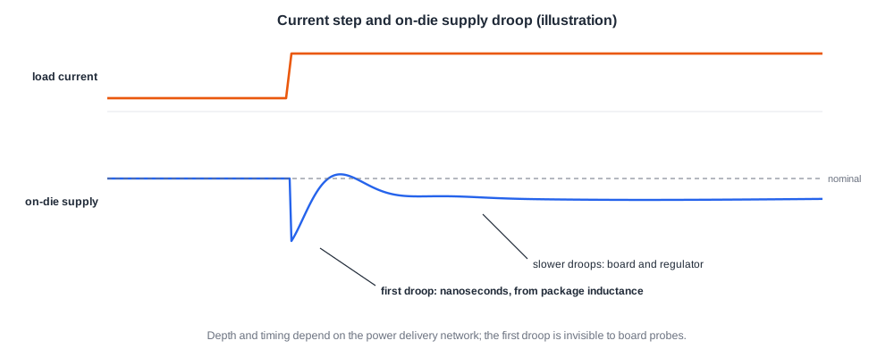
When the chip's current jumps, the inductance resists the change, and the voltage drops by L x dI/dt until the capacitors and the regulator catch up. A large chip moving from idle to full activity in a single cycle could, without on-die decoupling, see its supply collapse. A textbook example: a chip whose current rises from 20 A to 60 A in 1 ns through 20 pH of supply inductance would see 0.8 V of noise without on-die bypass capacitance.
Supply Impedance and Resonance
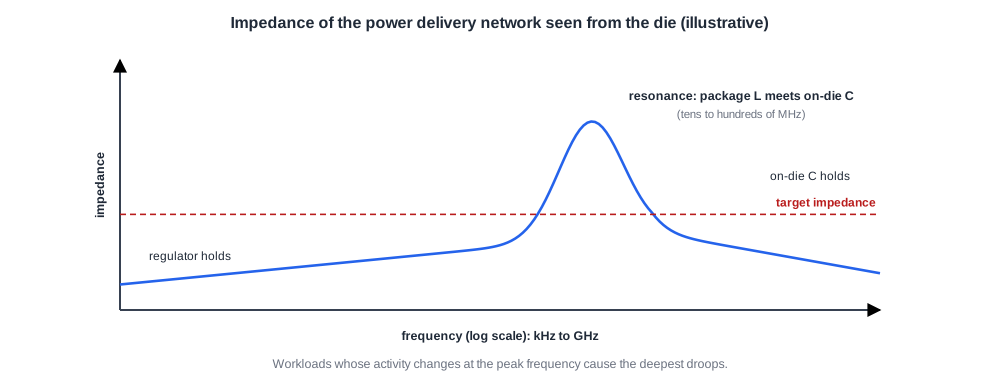
The power delivery network can be described by its impedance as seen from the die, across frequency. At low frequency the regulator holds the voltage; at very high frequency the on-die capacitance does.
In between, the package inductance and the on-die capacitance form a resonance, often in the tens to hundreds of megahertz. A current that changes at that frequency, for example a loop of activity that starts and stops at the resonant rate, makes the droop grow with each cycle. The peak of the impedance profile marks the most dangerous frequency.
Quick Check
Q: Why can a workload that switches between high and low activity at a particular rate cause a deeper droop than one that stays at full activity?
Show Answer
Constant full activity draws a steady current, which the regulator supplies with only a resistive drop. Activity that rises and falls at the resonant frequency of the power delivery network excites the resonance, so each cycle adds to the oscillation and the droop becomes much larger than one step alone would cause.
Measuring on the Die
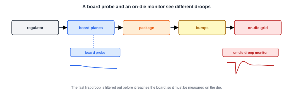
Board probes see the voltage on the board, after the regulator, but before the package and on-die grid. The fastest droops happen inside the package and die, and are filtered out by the time they reach the board.
So validation uses on-die droop monitors, described in Monitors on the Die: circuits that sense the local supply or detect when a delay line slows down. Some chips also bring a sense point out through a dedicated pin for oscilloscope measurements. Connecting droop detectors to the trace and cross-trigger logic lets a droop freeze the trace buffers, so the team can see what the chip was doing at that moment.
Stressing Power Delivery
Ordinary software rarely produces the worst current changes. Validation uses special workloads:
- Maximum-current loads that switch as much logic as possible.
- Step loads that go from idle to maximum in one cycle, many times.
- Resonance loads that toggle activity at the resonant frequency of the network, found by sweeping the toggle rate.
- Power-state transitions, waking blocks or turning on power switches, which cause large current steps.
Shmoos run under these loads show how much voltage margin the droop consumes, compared with quiet tests.
Quick Check
Q: A shmoo with a quiet test gives a minimum voltage of 0.78 V; under a resonance load it is 0.86 V. What does the difference mean?
Show Answer
About 80 mV of the supply is lost to dynamic droop under the worst workload. That droop must be included in the voltage margin: the product's minimum operating voltage has to cover 0.86 V plus other margins, not 0.78 V.
In Practice
When droop limits a product, teams have several options without new silicon: add or move board and package capacitors, tune the regulator's response, limit how fast blocks can change activity, or use adaptive clocking that slows the clock briefly when a droop is detected. The power planning and IR drop articles of the Physical Design tutorial, such as IR Drop: Static and Dynamic, describe the pre-silicon side of the same problem.
Common Mistakes
Mistake #1: Trusting board-level voltage probes
The fastest droops never reach the board. Measure on the die.
Mistake #2: Testing power delivery with ordinary software
Normal workloads rarely hit the worst current steps or the resonance. Use designed stress loads.
Mistake #3: Setting minimum voltage from quiet tests
Droop under real workloads eats into the margin. Include it.
Practice Exercise
Challenge: Inductive Droop
A block's current rises by 5 A in 2 ns. The effective inductance between the block and the nearest large decoupling is 10 pH.
Estimate the droop from L x dI/dt alone. What does on-die decoupling capacitance do to this number?
Hint
dI/dt = 5 A / 2 ns.
Solution
dI/dt = 2.5 x 10⁹ A/s, so the droop is 10 x 10-12 x 2.5 x 109 = 25 mV. On-die decoupling supplies the first part of the current step locally, so less current has to change through the inductance in that time and the real droop is smaller. Without it, the droop would be close to this estimate or larger.
Summary
- Sudden current changes through supply inductance make the on-die supply droop.
- The power delivery network has a resonance where the package inductance meets on-die capacitance; activity at that rate is worst.
- Fast droops must be measured on the die, with droop monitors that can trigger trace capture.
- Step, maximum-current, resonance and power-transition workloads stress power delivery.
- Droop consumes voltage margin and must be included in the minimum operating voltage.
