
A skew lot is a batch of wafers that the fab processes on purpose to land at the edges of the process window, making transistors faster or slower than normal. Testing parts from these wafers shows how the design behaves at the process corners it was signed off at, long before natural variation would produce such parts in volume.
Without skew lots, validation would only see the typical silicon that the first wafers happen to produce. This article explains how corner wafers are made, what each corner is used to check, and how teams know where a given part sits in the process.
6 min read | Intermediate
What You'll Learn
- Explain what a skew lot is and why it is ordered
- Name the process corners and what each one stresses
- Use process monitors to place a part in the process spread
- Plan which tests run on which corner parts
Why Corners Matter
Timing sign-off checks the design at process corners: slow transistors for setup, fast transistors for hold and leakage, and mixed corners where NMOS and PMOS differ. Those corners are a promise about every part that will ever ship.
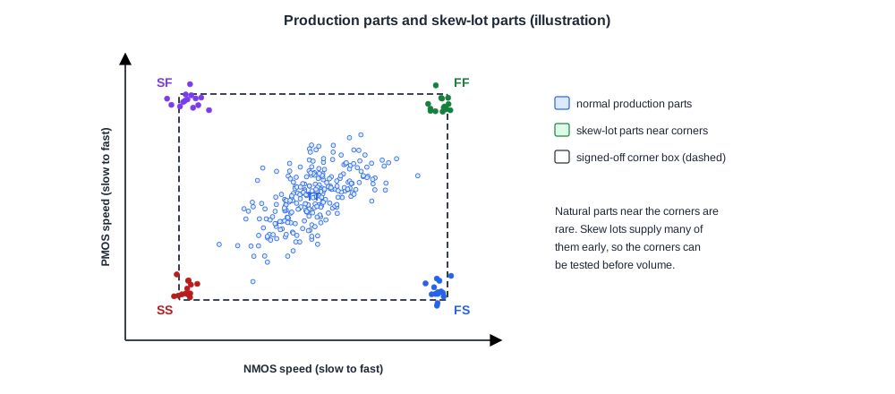
First silicon usually comes out near the typical point. A design that only works on typical parts will fail later, when production drifts to a corner. Skew lots let validation test the corners early and on purpose.
How a Skew Lot Is Made
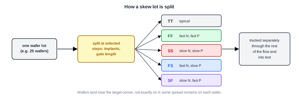
The fab splits a lot into groups and changes a few process steps for each group, such as channel implants or gate length, so that transistor speed moves in a controlled direction. The groups are tracked separately through the rest of the flow.
The usual targets are named by NMOS speed then PMOS speed:
- TT: typical NMOS, typical PMOS.
- FF and SS: both fast, or both slow.
- FS and SF: one fast and one slow, the mixed corners.
Real skew wafers rarely land exactly on the corner. They land near it, and some spread remains within each wafer.
Quick Check
Q: Why does validation not just wait for natural variation to produce corner parts?
Show Answer
Natural parts at the edge of the process are rare, perhaps a few per thousand, and they appear randomly over months of production. Skew lots produce many such parts at once, early enough that a design problem can still be fixed before volume shipment.
What Each Corner Checks
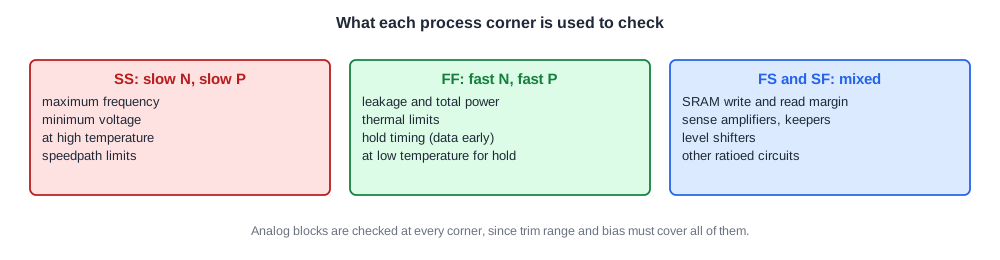
- SS parts set the speed limit. Shmoos at high temperature and low voltage show whether the slowest silicon still meets the frequency target.
- FF parts set the power and thermal limit. They leak the most and run hottest. They also stress hold timing, because data arrives early.
- FS and SF parts stress circuits that depend on a balance between NMOS and PMOS strength: SRAM cells and their write margin, sense amplifiers, keepers on dynamic nodes, and level shifters.
Analog blocks are checked at every corner, because trim range and bias currents have to cover all of them, as in PLLs and Analog Blocks on Silicon.
Knowing Where a Part Sits
Each part carries process monitors: ring oscillators built from standard cells, and simple transistor test structures. Their frequency or current shows how fast that piece of silicon is, independent of the design's logic.
Plotting a measured quantity such as maximum frequency against the ring oscillator frequency shows whether the design tracks the process. Parts that fall off the trend are interesting, because something other than transistor speed is limiting them.
Quick Check
Q: A memory fails writes on SF parts only, and passes on TT, FF and SS. What kind of circuit problem does this suggest?
Show Answer
A ratio problem. On SF silicon the NMOS is slow and the PMOS is fast, so in a typical SRAM cell the access transistor struggles to overpower the pull-up during a write. The write margin is too small at that mixed corner, which only shows when the two transistor types move in opposite directions.
In Practice
Skew lots are expensive and slow, so they are planned early, often started together with the first engineering wafers. Teams decide in advance how many parts from each corner go to each lab: speed and power characterization, I/O, analog, and reliability. The results feed directly into Fmax, Speed Bins and Binning and into the guard bands of production test.
Common Mistakes
Mistake #1: Testing only on early typical silicon
Corner problems appear later in production. Order skew lots early.
Mistake #2: Ignoring the mixed corners
FS and SF parts expose ratio problems that FF and SS never show.
Mistake #3: Trusting the wafer label instead of the monitors
Skew wafers land near, not on, the corner. Use ring oscillators to place each part.
Practice Exercise
Challenge: Plan the Corners
A team has 20 SS, 20 FF, 10 FS and 10 SF parts. Assign each group to one of these studies: maximum frequency at 110 °C, worst-case power under a power virus, SRAM minimum voltage, and hold-time margin at low temperature. Explain each choice.
Hint
Slow silicon limits speed; fast silicon limits power and hold.
Solution
SS parts for maximum frequency when hot, since slow transistors at high temperature set the speed limit. FF parts for worst-case power, since they leak most, and also for hold margin at low temperature, where data paths are fastest. FS and SF parts for SRAM minimum voltage, since cell stability and write margin depend on the NMOS to PMOS ratio.
Summary
- A skew lot is processed on purpose to produce parts near the process corners.
- Corners are named by NMOS then PMOS speed: TT, FF, SS, FS and SF.
- SS parts limit speed, FF parts limit power and hold, mixed corners expose ratio problems.
- Ring oscillators and test structures show where each part really sits.
