
Electrical validation checks that a chip's electrical behaviour stays within specification, with margin, under the worst conditions it will meet. Functional validation asks whether the logic is right; electrical validation asks whether the chip still works at the lowest voltage, the highest temperature, the slowest silicon and the noisiest board. This article describes what electrical validation covers, why it is statistical, and the loop of measuring, finding weak spots and tuning that drives it.
6 min read | Intermediate
What You'll Learn
- List the areas electrical validation covers
- Distinguish electrical failures from logic bugs and defects
- Explain why electrical validation needs many parts and conditions
- Describe the measure, find and tune loop
What It Covers
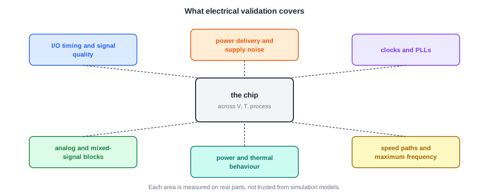
- I/O: timing at the pins, signal quality, eye diagrams and jitter, covered in I/O Characterization.
- Power delivery: supply noise and droop on the die, in Power Integrity on Silicon.
- Clocks: PLL lock, frequency and jitter.
- Analog and mixed-signal blocks: converters, references, sensors, in PLLs and Analog Blocks on Silicon.
- Power and thermal: how much power the chip draws and how hot it gets.
- Speed: the maximum frequency at each voltage and the paths that limit it.
Three Kinds of Failure
Failures on silicon fall into three classes:
- Manufacturing: a defect, or a part outside its parametric limits. It affects some parts, not all.
- Functional: a logic bug or a layout error that makes the chip fail under all conditions. These are usually the easiest to fix.
- Electrical: the logic is right, but the chip fails under certain conditions of voltage, temperature or frequency.
Electrical failures range from severe ones that look like functional bugs to rare ones that are extremely hard to reproduce. They are the main subject of this chapter.
Quick Check
Q: Every part fails a test at 0.9 V and passes at 1.0 V. Is that a functional or an electrical failure?
Show Answer
Electrical: the logic works, but only above a certain voltage. A functional bug would fail at every voltage. The next step is to find which path or circuit needs the higher voltage, usually with a shmoo plot.
It Is Statistical
A logic bug is the same on every part. Electrical behaviour varies from part to part, wafer to wafer and lot to lot, and with voltage and temperature. So electrical validation must cover the whole space of operating conditions, on enough parts to represent the process, including parts deliberately made at the process corners, as in Process Corners in Silicon: Skew Lots.
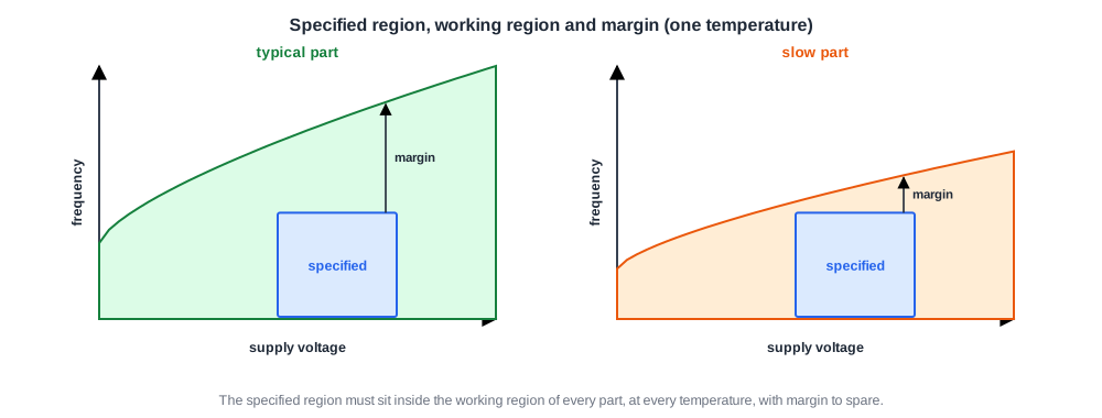
The quality bar is high. A production release typically requires the average defect level to be below about 50 parts per million, so a weakness that affects one part in ten thousand is a serious problem, even though few validation parts will ever show it.
The Loop
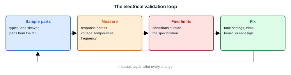
Electrical validation runs as a loop:
- Sample: measure a set of parts across voltage, temperature and frequency.
- Identify: find the conditions where behaviour falls outside the specification or margin is thin.
- Fix: tune settings such as drive strength, equalization or timing parameters, change a specification, or redesign for the next revision.
Then it repeats with the change. Many fixes are settings rather than silicon changes: I/O drive strengths, termination values, PLL parameters and memory timing are usually programmable for exactly this reason.
Quick Check
Q: Why are I/O drive strengths, termination and memory timing usually programmable rather than fixed in silicon?
Show Answer
Their best values depend on the real silicon, package and board, which are only known after first silicon. Programmable settings let electrical validation tune them, and let each product board use its own values, without a new silicon revision.
In Practice
Electrical validation labs automate everything: scripts drive supplies, temperature forcing units, testers and instruments, sweep conditions overnight and store every measurement. The output is a set of reports per area, each showing the margin to the specification across conditions and parts, which feeds the production release decision.
Common Mistakes
Mistake #1: Measuring only typical parts at room temperature
Problems hide at corners. Cover the full condition space on parts that span the process.
Mistake #2: Treating a voltage-dependent failure as a logic bug
If it passes at some conditions, it is electrical. Map it with shmoos before debugging logic.
Mistake #3: Fixing in silicon what a setting could fix
Many electrical issues are tuned with programmable settings. Check them before planning a respin.
Practice Exercise
Challenge: How Many Parts?
A weakness affects 1 part in 10,000. How many randomly chosen parts must be tested to have a 63 % chance of seeing at least one failing part? Use the fact that, for rare events, the chance of at least one occurrence in n trials is about 1 - e-n p.
Hint
1 - e-1 is about 0.63.
Solution
n p = 1 gives 63 %, so n = 10,000 parts. Validation never tests that many by hand, which is why rare weaknesses are found through corner parts, margin testing at extreme conditions, and production test data, rather than by luck.
Summary
- Electrical validation covers I/O, power delivery, clocks, analog blocks, power and thermal behaviour, and speed.
- Electrical failures depend on voltage, temperature or frequency; functional failures do not.
- It is statistical: many parts, process corners and the full condition space.
- It runs as a loop of sampling, identifying weak spots and tuning or redesigning.
