
A shmoo plot shows where a chip works and where it fails as two conditions are swept, most often supply voltage against clock frequency. Each point records pass or fail for a test.
The shape of the passing region says a lot: a healthy part works faster at higher voltage, and departures from that shape point to specific electrical problems. This article explains how shmoos are made, what a healthy one looks like, and how to read the common failure patterns.
7 min read | Intermediate
What You'll Learn
- Explain how a shmoo plot is produced
- Describe the shape of a healthy voltage-frequency shmoo
- Recognize the common failure patterns and their likely causes
- Read a temperature shmoo
Making a Shmoo
A test is run at each combination of two conditions, usually supply voltage on one axis and clock period or frequency on the other, and the result is recorded. A tester does this well, because it controls voltage and timing exactly, as in Validation Platforms.
Often only the vectors for one block are run, to examine that block. Other pairs of conditions are useful too: frequency against temperature, or input timing skew against the clock to find setup and hold limits at the pins.
A Healthy Shmoo
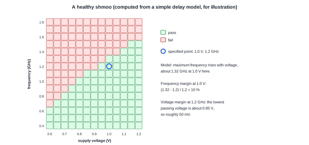
Transistors switch faster at higher voltage, so a healthy chip reaches a higher frequency as the voltage rises. The pass region forms a smooth boundary that rises from left to right.
The margin is the distance from the specified operating point to that boundary, in voltage at the specified frequency or in frequency at the specified voltage. A published shmoo of one low-power processor, for example, shows it working at 1.25 GHz at 0.75 V and at 2.5 GHz at 1.15 V.
Failure Patterns
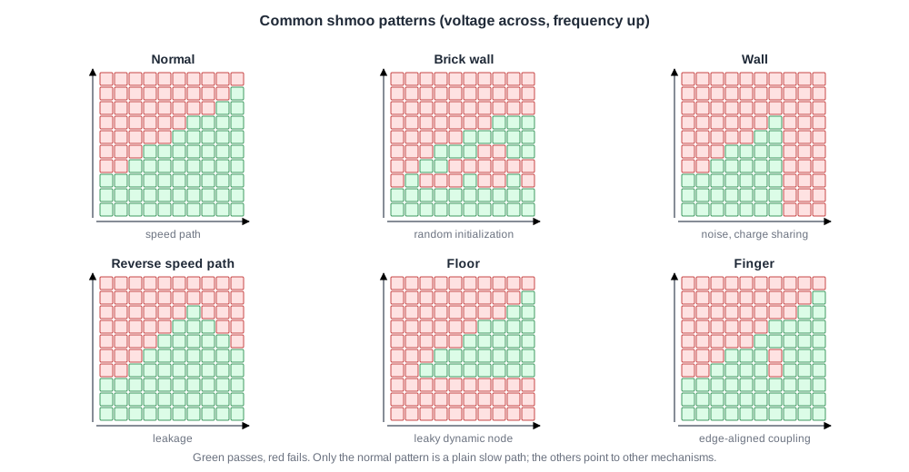
| Pattern | What it looks like | Likely cause |
|---|---|---|
| Normal | frequency rises smoothly with voltage | an ordinary speed path |
| Brick wall | pass and fail alternate irregularly | random initialization: a register without reset that powers up as 0 or 1 |
| Wall | fails at every frequency beyond a certain voltage | charge sharing, coupling noise or a race |
| Reverse speed path | higher voltage lowers the passing frequency | leakage: a weakly held node leaks away before the end of the cycle |
| Floor | fails at low frequency at every voltage | leakage on a dynamic or weakly held node |
| Finger | fails only at one spot | coupling that depends on how aggressor and victim edges line up |
The patterns guide debug. A wall or finger points away from logic and toward noise; a floor points to leakage; a brick wall to an uninitialized state.
Quick Check
Q: A block passes at high frequencies but fails below 200 MHz at every voltage. Which pattern is this, and what does it suggest?
Show Answer
A floor. At low frequency each cycle is long, so a weakly held or dynamic node has time to leak to the wrong level before it is used. The suspect is leakage in a dynamic or keeper-based circuit, not a slow path.
Temperature Shmoos
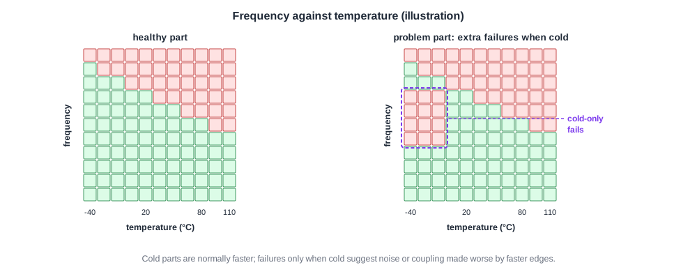
Plotting frequency against temperature adds more clues. Transistors are normally faster when cold, so a healthy part's maximum frequency rises as temperature falls.
- Failures when cold can mean coupling or charge-sharing noise made worse by faster edges.
- Failures when hot can mean leakage or noise made worse by lower threshold voltages.
- Walls at one temperature can mean a race whose winner changes with temperature.
Quick Check
Q: At the specified 1.0 V, the shmoo boundary is at 1.32 GHz and the product is specified at 1.2 GHz. What is the frequency margin in percent?
Show Answer
(1.32 - 1.2) / 1.2 = 10 %. Whether that is enough depends on how much slower the slowest production parts and the worst conditions are than this part, which is why shmoos are repeated on many parts and corners.
In Practice
Teams run shmoos on many parts and overlay them, so the spread between parts is visible. The worst boundary across parts, conditions and tests sets the real margin.
Different tests give different boundaries: a test that exercises the critical path shows the true limit, while an easy test may pass far beyond it. Shmoos therefore use the most demanding tests available, as in Speedpaths.
Common Mistakes
Mistake #1: Shmooing with an easy test
A test that misses the critical path overstates the margin. Use the most demanding tests.
Mistake #2: One part, one temperature
Margins vary with part and temperature. Overlay many parts and temperatures.
Mistake #3: Treating every failure region as a slow path
Walls, floors and fingers point to noise, leakage and coupling. Read the pattern first.
Practice Exercise
Challenge: Read the Pattern
A shmoo shows a normal rising boundary, except that above 1.15 V the passing frequency starts to fall again as voltage increases. What pattern is this, what is the likely mechanism, and what would a temperature shmoo be expected to show?
Hint
More voltage should help speed, not hurt it.
Solution
A reverse speed path. Higher voltage increases leakage, so a weakly held node leaks to an invalid level within a shorter time, and the part fails at shorter periods as voltage rises. Leakage also grows strongly with temperature, so the temperature shmoo should show the problem worsening when hot.
Summary
- A shmoo records pass or fail across two swept conditions, usually voltage and frequency.
- A healthy part's maximum frequency rises smoothly with voltage; margin is the distance from the operating point to the boundary.
- Brick walls, walls, reverse speed paths, floors and fingers point to initialization, noise, leakage and coupling problems.
- Temperature shmoos separate noise problems when cold from leakage problems when hot.
