
A validation platform is the hardware a chip sits in while it is tested: a production-style tester, a bench board covered in test points, or a board that looks like the final product. Each answers different questions.
Testers give precise control of every pin, debug boards give access and flexibility, and system boards run real software in a realistic setting. This article describes the three kinds, the fixtures that connect a chip to them, and the equipment around them.
7 min read | Beginner
What You'll Learn
- Compare testers, debug boards and system boards
- Name the fixtures that connect a chip to each platform
- Describe what a good debug board provides
- List the lab equipment used around the platforms
Three Kinds of Platform
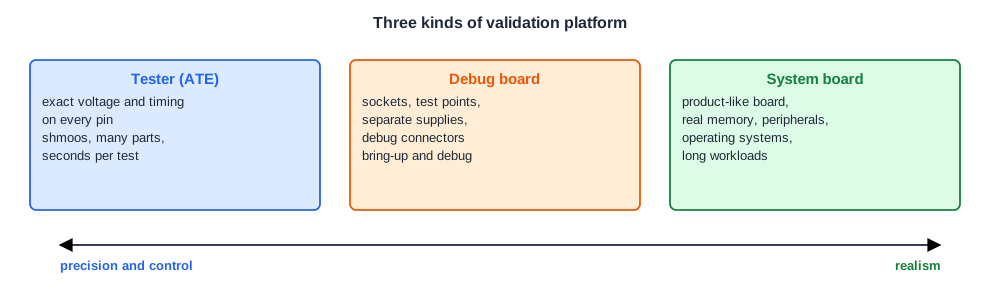
| Tester (ATE) | Debug board | System board | |
|---|---|---|---|
| Strength | exact control of every pin's voltage and timing | access: sockets, test points, adjustable supplies | realism: real memory, peripherals and software |
| Typical tests | pattern tests, shmoos, characterization of many parts | power-on, bring-up, debug of hard failures | operating systems, applications, compatibility |
| Test length | seconds per part | minutes to days | hours to weeks |
| Quantity | few, expensive | dozens | many |
Most validation programs use all three. Electrical and characterization teams live on testers and benches, bring-up and debug engineers on debug boards, and compatibility and software teams on system boards.
Testers
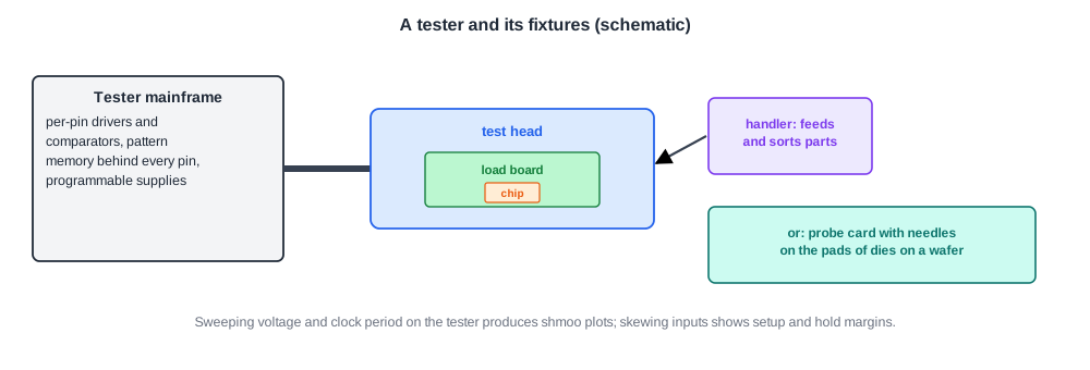
A production tester, or automatic test equipment (ATE), applies stimuli to every pin of the chip and records the responses. Each tester pin has its own drivers, comparators and pattern memory, so the voltage levels and timing of every signal can be set individually.
That control is what makes testers good for characterization. Sweeping the supply voltage and the clock period while repeating a test produces a shmoo plot, the subject of Shmoo Plots. Skewing input timing against the clock shows setup and hold margins at the pins.
Testers are expensive, and their time is billed. A tester costing 5 million dollars and used for two years costs about 8 cents per second, which is why production tests are kept short. Smaller engineering testers with fewer features are common in validation labs.
Fixtures
A fixture connects the chip to the platform. Four kinds are common:
- Probe card: fine needles that touch the pads of a die on the wafer, for testing before packaging.
- Load board: a board on the tester's test head with a socket for a packaged part.
- Bench board: a printed circuit board for tests in the lab, with or without a tester.
- System board: the chip in its real application, showing the product working.
Sockets matter a great deal. A socket lets one board test many parts, which is essential for separating a bad part from a bad board, but it adds inductance and resistance compared with a soldered part.
Quick Check
Q: Why are early debug boards usually built with sockets, even though soldered parts give better electrical performance?
Show Answer
Parts must be swapped often: to test many parts on one board, to replace a damaged part, and to tell whether a failure belongs to the part or to the board. Sockets make that a matter of minutes instead of rework. Soldered parts come later, on system boards, where realism matters more.
What a Good Debug Board Provides

A debug board is designed for access and flexibility rather than size or cost:
- Separate, programmable supplies for each power rail, with current measurement, so each rail can be turned on alone, ramped slowly and current-limited.
- Clock options: an on-board oscillator, an external clock input, and a way to bypass internal PLLs.
- Switches and jumpers for reset, boot mode and configuration pins, so the chip can start in its simplest mode.
- Debug connectors for JTAG and trace, as in Debug Access: JTAG, Debug Ports and Scan Dump.
- Test points on key signals and supplies, for oscilloscopes and logic analyzers.
- Connectors for memory, peripherals and add-in cards, so features can be added one at a time.
A board missing any of these turns into hours of rework during bring-up. Board designers and validation engineers therefore review the board schematic together, against the validation plan.
Lab Equipment
Around the platforms sits a set of instruments:
- Oscilloscopes and logic analyzers for signals at the pins.
- Power analyzers and current probes for supply currents and power.
- Temperature forcing units and chambers that heat or cool the chip to set junction temperatures.
- Signal generators, bit error rate testers and network analyzers for high-speed interfaces and analog blocks.
- Debug probes that connect a host computer to the chip's debug port.
Scripts tie them together, so that a test can sweep voltage, frequency and temperature automatically and log every result.
Quick Check
Q: A failure appears only on system boards running an operating system, never on the debug board. Name two possible reasons.
Show Answer
The system board runs real, long, complex software that exercises interactions the debug board's tests do not. Its power delivery, memory or peripherals also differ: a weaker supply, a different memory part or a noisier environment can expose an electrical margin. Moving the failing software to the debug board, or the debug board's settings to the system board, separates the two.
In Practice
The number of boards is often the real limit in the first weeks. Teams plan board counts per team in the validation plan and share the most capable debug setups through a booking system. A few boards are kept as known-good references, never modified, so that any new problem can be checked on a setup everyone trusts.
Common Mistakes
Mistake #1: One shared supply for all rails
Without separate supplies, rails cannot be powered or measured one at a time, and a short on one rail cannot be found.
Mistake #2: Too few boards
Boards take months to build. Plan enough for every team, plus spares and known-good references.
Mistake #3: Testing only on one platform
Each platform hides some problems. Move failures between tester, debug board and system board to understand them.
Practice Exercise
Challenge: Match the Platform
Which platform fits best: (a) measuring the setup time of an input pin across voltage on 200 parts; (b) the first power-on of a new chip; (c) running a video application for 48 hours with many USB devices attached?
Hint
Think precision, access, realism.
Solution
(a) A tester: exact control of pin timing and voltage, and seconds per part for 200 parts. (b) A debug board: separate supplies, clock options and debug access. (c) A system board: real software and peripherals for a long run.
Summary
- Testers give exact per-pin control, debug boards give access, system boards give realism.
- Fixtures include probe cards, load boards, bench boards and system boards; sockets let parts be swapped.
- A good debug board has separate programmable supplies, clock options, configuration switches, debug connectors and test points.
- Instruments and scripts sweep voltage, frequency and temperature and log every result.
