
Burn-in runs chips at high temperature and high voltage for a period before shipping, so that weak parts with hidden defects fail in the factory rather than in a customer's system. It targets the infant mortality part of the bathtub curve.
Burn-in is expensive and stresses the design in unusual ways. This article explains what burn-in does, the conditions it uses, what the design must support, and how teams try to reduce or replace it.
6 min read | Intermediate
What You'll Learn
- Explain why burn-in removes infant mortality
- Describe typical burn-in conditions
- List the design requirements burn-in imposes
- Compare burn-in with other screening methods
Why Burn-In
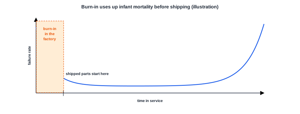
Some parts leave the fab with defects that do not fail any test yet: a thin spot in an oxide, a partly formed via, a tiny particle. These weak parts fail early in life.
Burn-in ages every part quickly under high stress, so most weak parts fail before shipping. The parts that survive start their life in the flat part of the bathtub curve.
Conditions
Typical burn-in conditions are an external temperature of about 125 to 140 °C, with an even higher junction temperature, and a supply of about 1.3 to 1.7 times nominal. Parts run for hours, in large ovens holding many boards of sockets.
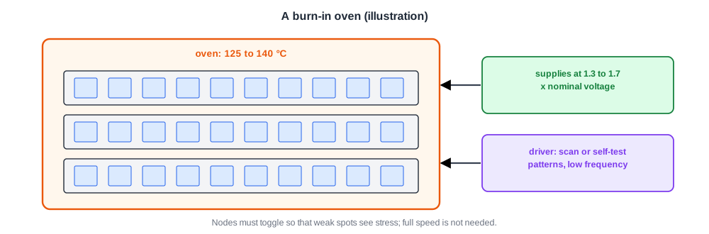
The chips do not need to run at full speed, but they must operate correctly at a lower frequency so that internal nodes toggle and see stress. Burn-in drivers apply patterns, often through scan or built-in self-test, and monitor for failures.
Quick Check
Q: Why must chips toggle during burn-in rather than simply sit powered?
Show Answer
Many weak spots only fail when stressed in both states or when current flows through them. Toggling puts each node through both values and exercises the transistors and wires, so more defects are activated. Static powering would stress only one state of each node.
What It Demands of the Design
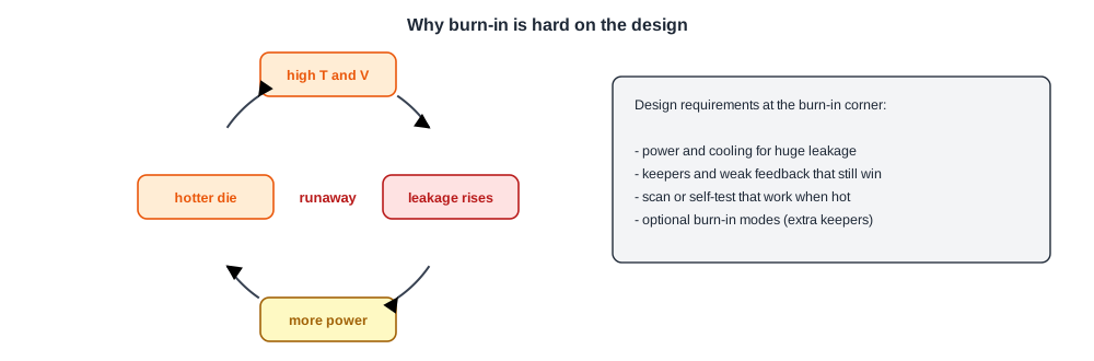
- Leakage: at burn-in temperature and voltage, leakage is enormous. Total power can exceed what the sockets and boards can cool, and rising temperature raises leakage further, which can lead to thermal runaway.
- Weak circuits: keepers on dynamic nodes and weak feedback in latches must still win against the huge leakage. The burn-in corner can set their size.
- Test access: scan and built-in self-test must work at burn-in conditions to toggle the logic.
Some designs add special burn-in modes, such as extra keepers turned on only during burn-in.
Quick Check
Q: A chip that draws 15 W of leakage at burn-in conditions sits in sockets limited to 10 W each. What can be done?
Show Answer
Reduce the stress, for example lower voltage or temperature with a longer burn-in time, power-gate idle blocks during burn-in, or use sockets with better cooling. Running at 15 W risks thermal runaway and damaging good parts.
Reducing Burn-In
Burn-in costs oven time, boards and test, and slightly ages every good part. Teams therefore try to shorten or replace it with other screens:
- Voltage stress during normal test: a short high-voltage pulse activates some weak oxides.
- Quiescent current testing: a part with abnormal standby current may contain a defect.
- Outlier screening: parts far from their population, as in Characterizing Many Parts, are rejected.
Early life failure data from qualification shows whether these screens are enough.
In Practice
Burn-in decisions balance cost against the reliability customers require. High-reliability markets such as automotive and servers usually keep burn-in longer. Because burn-in locks in much of the early NBTI shift described in Aging on Silicon, test after burn-in sees parts closer to their aged speed.
Common Mistakes
Mistake #1: Designing only for normal corners
Keepers and latches must work at the burn-in corner too.
Mistake #2: Ignoring burn-in power
Leakage at burn-in can cause thermal runaway. Plan power and cooling.
Mistake #3: Dropping burn-in without data
Use early life failure data to show alternative screens are sufficient.
Practice Exercise
Challenge: Burn-In Time
Weak parts in the field would fail within the first 2,000 hours. Burn-in conditions accelerate their failure mechanism by a factor of 400.
How long must burn-in run to cover that period? If the acceleration falls to 100 to save power, how long?
Hint
Burn-in time = field hours / acceleration.
Solution
2,000 / 400 = 5 hours. At an acceleration of 100, 20 hours, four times the oven time.
Lower stress saves power but costs throughput. The numbers are assumptions for the exercise.
Summary
- Burn-in stresses parts to make weak ones fail before shipping.
- Typical conditions are 125 to 140 °C and 1.3 to 1.7 times nominal voltage, with toggling at low speed.
- The design must cope with huge leakage, thermal runaway risk and weak circuits at that corner.
- Voltage stress, current testing and outlier screening can shorten or replace burn-in.
