
Clock architecture is the plan for how an SoC makes and distributes its clocks: which sources exist, how many clock domains there are, how frequencies are derived, and how clocks are switched and gated. Wherever a signal passes from one clock domain to another, it crosses a boundary that ordinary design rules don't protect, and a wrong crossing can fail at random in silicon. This article explains clock sources and trees, why chips have many domains, what metastability is and how much a synchronizer helps, and the standard circuits for passing single bits, multi-bit values and streams of data between domains.
12 min read | Intermediate
What You'll Learn
- Describe the clock sources, generators and trees of an SoC
- Explain metastability and calculate how much a synchronizer improves reliability
- Choose the right crossing circuit for a bit, a bus or a data stream
- Describe clock gating and safe clock switching
Where Clocks Come From
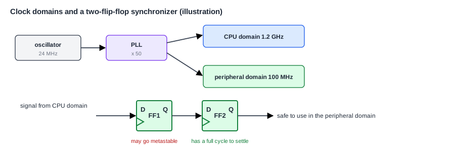
Clocks and Resets in a System introduced the basics. A chip's clocks start from a reference: usually a crystal oscillator on the board, at a modest frequency such as 24 MHz, and often a 32.768 kHz crystal for timekeeping in sleep. On the chip, PLLs (phase-locked loops) multiply the reference up to the frequencies blocks need, gigahertz for the CPUs, hundreds of megahertz for buses, and specific values for interfaces such as USB or audio. Dividers derive slower clocks from faster ones.
Each clock reaches thousands to millions of flip-flops through a clock tree, a network of buffers built during physical design so that the clock edge arrives at all flip-flops at nearly the same time. The remaining difference in arrival time is called skew, and timing analysis must account for it, as the Static Timing Analysis tutorial explains. Clock trees use a large share of a chip's dynamic power, because they switch every cycle.
Why So Many Domains
A clock domain is the set of flip-flops driven by one clock, or by clocks with a fixed, known relationship. A large SoC can have dozens of domains, for good reasons:
- Different blocks need different speeds. Running a UART at CPU speed would waste power.
- Interfaces have their own fixed rates: USB, audio, Ethernet and display timing each need exact frequencies.
- Some clocks come from outside, such as data arriving from a camera with its own clock.
- Frequency scaling changes the CPU's clock independently of everything else, as Dynamic Voltage and Frequency Scaling explains.
- Blocks that are powered down lose their clock, while the always-on domain keeps its own.
Within one domain, static timing analysis guarantees that every signal arrives in time. Between domains whose clocks have no fixed relationship, it can't: the edges drift past each other, and sooner or later a signal will change just as the receiving flip-flop samples it.
Metastability
A flip-flop needs its input stable for a short time around the clock edge, its setup and hold window. If the input changes inside that window, the flip-flop can enter a metastable state: its output hovers between 0 and 1 for an unpredictable time before settling either way. If logic uses that output before it settles, different parts of the logic may see different values, and the design behaves wrongly. Synchronizers and Clock Domain Crossing in the Digital Fundamentals tutorial shows the circuit-level picture.
Metastability can't be prevented, only made very unlikely. The probability that a flip-flop is still unresolved after a time t falls exponentially with t. The mean time between failures (MTBF) of a synchronizer is commonly written:
MTBF = e^(t / tau) / (T0 x f_clk x f_data)
Here tau and T0 are properties of the flip-flop, f_clk is the receiving clock and f_data the rate at which the input changes, and t is the time allowed for the flip-flop to settle before the next stage samples it.
Why Two Flip-Flops
A synchronizer gives the first flip-flop time to settle by adding a second one after it: the second samples the first a whole clock cycle later, by which time the first has almost certainly resolved. The difference is enormous, because the time appears in an exponent. With assumed values for a fast process (tau of 20 ps, T0 of 0.1 ns, a 1 GHz receiving clock, data changing at 100 MHz), a single flip-flop with 0.6 ns to settle gives an MTBF of about 12 days. Adding a second flip-flop gives another nanosecond to settle, and the MTBF rises to about 1020 years. These numbers are assumptions for this example, and real values come from the library and the timing, but the lesson always holds: one flip-flop is not enough, and two are usually plenty. Very fast clocks, or safety-critical designs, use three.
Quick Check
Q: A chip has 10,000 single-flip-flop crossings, each with an MTBF of 12 days. What is the MTBF of the chip?
Show Answer
Failures add up across crossings: 12 days / 10,000 is about 104 seconds. The chip would fail every couple of minutes. That is why every crossing needs a proper synchronizer.
Crossing Single Bits
A single control signal, such as an enable or an interrupt, crosses through a two-flip-flop synchronizer. Two rules apply. The signal must come straight from a flip-flop in the source domain, not from combinational logic, which could produce short glitches that the receiver might catch. And the signal must stay stable long enough for the receiver to see it. A pulse shorter than the receiving clock's period may be missed entirely. A short pulse is therefore converted to a level change, or stretched, or passed with a handshake, before it crosses.
Crossing Multi-Bit Values
Synchronizing each bit of a bus separately does not work. The bits settle independently, so during a change, the receiver can capture some bits from the old value and some from the new, a value that never existed. There are three standard solutions:
- Gray code. For a counter, encode it so that only one bit changes at each step, as Gray code does. Then the receiver sees either the old value or the new one, never a mixture. This is how FIFO pointers cross.
- Handshake. Hold the data stable in the source domain, and send a single synchronized "valid" signal. The receiver samples the data once it sees valid, then returns a synchronized "acknowledge". It is safe for any data, but slow: each transfer takes several cycles of both clocks.
- Asynchronous FIFO. For a stream of data, use a FIFO whose write side runs on one clock and read side on the other.
The Asynchronous FIFO
An asynchronous FIFO is the standard way to pass a stream of data between domains. Its storage is a small dual-port memory. The writer advances a write pointer in its own domain, and the reader advances a read pointer in its. To know whether the FIFO is full, the writer needs the read pointer, and to know whether it is empty, the reader needs the write pointer. Each pointer is converted to Gray code and passed through a synchronizer to the other side. The data itself never needs synchronizing: by the time the reader sees the pointer move, the data has been written and is stable.
The synchronized pointers are a few cycles old, so each side sees a slightly pessimistic view: the writer may think the FIFO is full a little longer than it is, and the reader that it is empty a little longer. That costs a little throughput, never correctness. The depth is chosen to cover the worst-case burst and the synchronizer delay. The RTL Synthesis tutorial shows an implementation, and Bridges and Clock Domain Crossing shows how bus bridges use these FIFOs.
Where Does This Matter?
Clock domain crossing bugs are among the most dangerous in chip design, because they pass every simulation, which never models metastability, and then fail rarely and randomly in silicon. Teams therefore run dedicated CDC tools on every design. These find every crossing structurally, check that each passes through an approved synchronizer, and flag reconvergence, where two separately synchronized signals are later combined and can disagree for a cycle. Some tools also inject random delays at crossings in simulation, to expose logic that assumes a fixed latency.
Clock Gating
Since clock trees use so much power, idle logic should not receive a clock. Clock gating stops the clock to a block, or a group of registers, when it has nothing to do. Gating is done with a special integrated clock gating cell that includes a latch, so that the gate can only change while the clock is low, and never creates a short glitch. Synthesis tools insert fine-grained gates automatically, wherever a register's enable shows it holds its value. Coarse-grained gating, turning off whole blocks, is controlled by software or a power manager.
A plain AND gate on a clock is a classic beginner's bug: if the enable changes while the clock is high, the output produces a shortened pulse, which can clock some flip-flops and not others.
Switching Clocks Safely
Sometimes a block's clock must change source while it is running, for example from the reference clock to a PLL after it locks, or to a slower source to save power. A plain multiplexer between two clocks can produce a glitch at the switch, a shortened high or low phase that violates the flip-flops' timing. A glitch-free clock multiplexer waits for the current clock to go low, stops it, then waits for the new clock to go low before enabling it, with synchronizers on each side. Every SoC's clock controller is built from such multiplexers, dividers and gates, and controlled by software through registers.
Planning the Clocks
Clock architecture is decided early and written in the spec: the list of sources and PLLs, every domain with its frequency range, which domains each block belongs to, every crossing between them, and which domains can be gated or switched. The list of crossings is then the input to the CDC checks. Keeping the number of domains and crossings no larger than needed is one of the best ways to reduce risk, since each crossing is a place where a subtle bug can hide.
Quick Check
Q: A 4-bit counter in one domain is passed to another by synchronizing each bit with two flip-flops. The counter changes from 0111 to 1000. What can the receiver see?
Show Answer
All four bits change, and each synchronizer may resolve differently, so the receiver may see any mixture, such as 1111 or 0000, values that never existed. In Gray code, only one bit changes per step, so the receiver sees either the old or the new value.
Common Mistakes
Mistake #1: Synchronizing a bus bit by bit
The bits settle independently, so the receiver can see an invalid mixture. Use Gray code, a handshake or an asynchronous FIFO.
Mistake #2: Driving a crossing from combinational logic
Glitches from logic can be captured by the receiving domain. Every signal that crosses must come straight from a flip-flop in its source domain.
Mistake #3: Gating a clock with a plain AND gate
An enable that changes while the clock is high creates a glitch. Use an integrated clock gating cell.
Practice Exercise
Challenge: Size an Asynchronous FIFO
A camera interface writes 16-bit pixels at 200 MHz in bursts of 1,920 pixels per line, then pauses. An image processor reads one pixel per cycle at 150 MHz. These numbers are assumptions for this exercise. (a) During a line, how fast does the FIFO fill? (b) How deep must it be to hold the excess of one line? (c) What other delay should be added to the depth? (d) Why does the data itself not need synchronizers?
Hint
A line lasts 1,920 / 200 MHz. In that time the reader takes 150 MHz x that time.
Solution
(a) It gains 200 - 150 = 50 million pixels per second while a line is arriving. (b) A line lasts 9.6 µs, during which the reader takes 1,440 pixels, so 480 pixels pile up: at least 480 entries. (c) The few cycles of synchronizer delay on the pointers, during which each side sees an out-of-date pointer, so add a small margin, for example rounding up to 512. (d) Data is written before the write pointer moves, and the reader only reads entries it sees as written, by which time the data has been stable for several cycles.
Summary
- Clocks start at crystals, are multiplied by PLLs, divided, and distributed through clock trees.
- An SoC has many clock domains, and timing analysis can't protect signals that cross between them.
- Metastability can only be made rare; a second flip-flop raises the MTBF from days to astronomically long in a typical case.
- Single bits use two-flip-flop synchronizers; multi-bit values use Gray code, handshakes or asynchronous FIFOs.
- Clocks are gated with integrated gating cells and switched with glitch-free multiplexers.
