
When an SoC is switched on, its RAM holds random values, its clocks may be running at a slow default, and the program it is supposed to run sits in a flash chip on the board that the processor cannot yet read. Something must bring the system from that state to a running program, and it has to work every single time, on every chip, before any software can help. That is the job of the boot flow: a chain of small programs, starting with code built into the chip itself. This article explains the reset vector, what a boot ROM does step by step, how secure boot builds a chain of trust, what the start-up code before main must do, and how chips are booted in simulation, using the section layout of a small program.
13 min read | Beginner to Intermediate
What You'll Learn
- Explain the reset vector and why an SoC needs a boot ROM
- Describe the boot stages from reset to the operating system or application
- Explain secure boot and the chain of trust
- List what start-up code must do before main, from a program's sections
The First Instruction
After reset, a processor fetches its first instruction from a fixed address, the reset vector. The ISA may define it or leave it to the chip; RISC-V leaves it to each implementation, and many small cores use address 0. Whatever is at that address runs first, with no operating system, no initialized memory and no help.
The difficulty is that most memories cannot provide that first instruction. SRAM and DRAM lose their contents without power, so at power-on they hold random values. DRAM cannot even be used until its controller has been configured and, for modern DRAM, trained to the board's signal timing. The product's software lives in flash, but flash interfaces such as SPI or eMMC need to be set up and driven by software before they deliver data. Something must run first that is always there, already correct, and needs nothing else.
The Boot ROM
That something is the boot ROM: a small read-only memory on the die, placed at the reset vector, whose content is fixed when the chip is manufactured. Its program is the first code every chip runs. Because it cannot be changed after tape-out, it is kept small, typically tens of kilobytes, and verified with extreme care. A bug in the boot ROM is a bug in every chip ever made from those masks.
A typical boot ROM does the following:
- Minimal setup. Set the stack pointer to a small on-chip SRAM, configure the clocks to a safe speed, and often switch on a watchdog timer, so that a boot that hangs resets the chip instead of freezing it.
- Choose a boot device. Read the boot mode: a few pins sampled at reset (strap pins) or bits in one-time-programmable fuses, which say whether to boot from SPI flash, eMMC, an SD card, USB or a serial port. Many chips also have a recovery mode that waits for an image over USB or UART, so that a board with an empty or broken flash can still be programmed.
- Load the next stage. Initialize that device's controller with conservative settings and copy the next boot stage, a small program, into on-chip SRAM.
- Verify it. On chips with secure boot, check the image's cryptographic signature (see below). If it fails, try a backup image or enter recovery mode.
- Jump. Start the next stage at its entry address.
The boot ROM is therefore part of the SoC architecture, with its own spec: supported boot devices, boot-mode pins, the image format it expects, timeouts, what it does on errors. The architects decide which interfaces it supports, because a boot device the ROM cannot read can never be used to boot.
The Boot Stages
A larger system boots in several stages, each one able to do more than the one before:
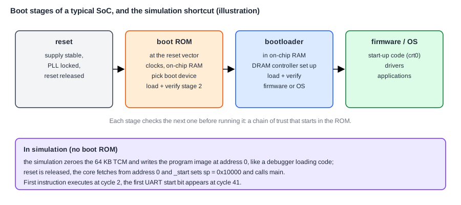
The boot ROM loads a bootloader into on-chip SRAM. The bootloader is ordinary software, stored in flash and updatable with the product. It sets up the DRAM controller, so that the system now has gigabytes of memory instead of a few hundred kilobytes, initializes more devices, and then loads the operating system kernel or the application firmware into DRAM and starts it. Phones and PCs have even more stages, but the principle is the same: each stage brings up just enough of the system to load the next.
Small microcontrollers often have a simpler flow. Their program is in on-chip or memory-mapped NOR flash, which the processor can read like memory from the first cycle. The reset vector points straight into flash, and the program executes in place without being copied, with only a small ROM, or none, in front of it.
Quick Check
Q: Why does the boot ROM load the bootloader into on-chip SRAM rather than into DRAM?
Show Answer
DRAM cannot be used yet: its controller must first be configured and trained, which takes code that knows the board's memory chips. That code is in the bootloader. On-chip SRAM works immediately after reset, so the first loaded stage runs there and then makes DRAM usable.
Secure Boot and the Chain of Trust
If anyone can replace the flash content, anyone can make the chip run their own code, which for a phone, a car or a payment terminal is unacceptable. Secure boot makes every stage check the next one before running it.
The product's maker signs each boot image with a private key that never leaves the company. The chip holds the matching public key, or a cryptographic hash of it, in fuses programmed at the factory, which cannot be changed afterwards. The boot ROM computes a hash of the loaded image and checks the signature with the public key. Only if it matches does it run the image. The bootloader checks the operating system the same way, and so on.
This is a chain of trust, and its first link, the root of trust, is the boot ROM together with the fused key. Because the ROM is part of the silicon and cannot be modified, an attacker who changes the flash cannot break the first link. Most secure-boot designs add anti-rollback protection, a version counter in fuses, so that an old, signed but vulnerable image cannot be reinstalled. The security subsystem of an SoC, with its key storage and cryptographic hardware, exists largely to make this chain work.
Where Does This Matter?
Boot ROM bugs are among the most serious a chip can have, precisely because they cannot be fixed: several well-known game consoles and phones have had boot ROM flaws that allowed their secure boot to be bypassed on every unit ever sold. Teams therefore keep boot ROMs minimal, review them line by line, and verify every path, including the error and recovery paths, in simulation and emulation long before tape-out.
Before main: Start-Up Code
Whichever stage finally starts the application, a C program cannot begin at main directly. A short piece of assembly code, the start-up code, usually called crt0 (C run-time zero), runs first and creates the environment C expects. To see what it must do, look at what a compiled program contains. The linker groups a program into sections:
| Section | Contains | In the image? | Start-up code must |
|---|---|---|---|
| .text | machine code | yes | nothing (it is already in place, or copied by the loader) |
| .rodata | constants, such as strings | yes | nothing |
| .data | global variables with initial values | yes, the initial values | copy them from where the image was stored into RAM, if the image is in ROM or flash |
| .bss | global variables that start at zero | no, only their size | fill them with zeros |
| stack | local variables, return addresses | no | set the stack pointer to the top of its region |
Two small programs show the difference. One that prints text has a few hundred bytes of code and some constant strings, and no .data and no .bss: its buffer is in a separate SRAM, reached through a pointer. A program that copies a buffer has only 160 bytes of code but 8 KB of .bss for its two 4 KB arrays, so its memory use is about fifty times its image:
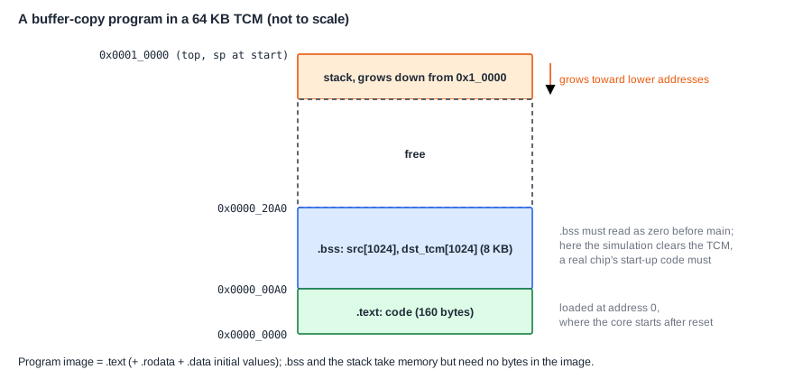
The 8 KB of .bss take memory, but not a single byte of the image: the image only records where they are and how large. That is why every C program's start-up code has to clear .bss. C guarantees that a global variable without an initializer starts at zero, and only the start-up code can make that true.
A Minimal Start-Up Code
On a small SoC under simulation, the start-up code can be as short as five instructions:
_start:
    li   sp, 0x10000          # stack at the top of the 64 KB TCM
    call main
    li   t0, 0x4000F000       # simulation control: EXIT register
    sw   a0, 0(t0)            # report main's return value, end the test
1:  j    1b                   # stay here if nothing stops the processor
It sets the stack pointer, calls main, and reports main's result. It does not copy .data and does not clear .bss. It can skip both because of how the chip is booted in simulation: the simulation first writes zeros to all of the TCM, then writes the program image at address 0, then releases reset. Every .bss variable is therefore already zero, and initialized data is already in place, because the image was loaded into the memory the program runs from. A chip that boots from ROM or flash has none of this help, and its start-up code adds two loops before calling main: one that copies the .data initial values from the image into RAM, and one that writes zeros over .bss, using addresses that the linker script provides as symbols.
Booting in Simulation
During chip design, the simulation environment often plays the role of the boot ROM, loading the program directly into the TCM the way a debugger can write code into a chip's memory through its debug port. This direct loading, often called backdoor loading, is standard practice in SoC verification: simulating a real boot from a flash model takes a long time, so most tests start with the program already in memory, while a smaller set of tests checks the real boot path.
Booted this way, a small SoC can reach main within a few cycles of reset and print its first UART bit in a few dozen. Clocks and Resets in a System follows those cycles one by one. A real boot from flash takes milliseconds rather than nanoseconds, because of the steps this article describes.
Quick Check
Q: The buffer-copy program is moved into a chip that boots from flash, and its start-up code is the five instructions above. What can go wrong?
Show Answer
Its 8 KB of .bss would contain whatever the RAM held at power-on, not zeros, because nothing clears them. The program fills src before using it, so it might still work, but any code that relies on a global starting at zero would fail randomly. The start-up code needs a .bss-clearing loop, and a .data copy loop if the program has initialized globals.
Common Mistakes
Mistake #1: Putting too much into the boot ROM
Every line in the ROM is permanent. Keep it to the minimum needed to load and verify the next stage, and put everything else in updatable firmware.
Mistake #2: Forgetting the recovery path
A chip whose ROM can only boot from flash cannot be rescued if the flash is empty or corrupted. Provide a recovery boot mode over a simple interface such as USB or UART.
Mistake #3: Testing only with backdoor loading
Tests that preload memory never exercise the boot ROM, the flash controller or the start-up code. Reserve tests that boot the real way, from reset through every stage.
Practice Exercise
Challenge: How Long Does Boot Take?
A chip boots a 256 KB firmware image from a quad SPI flash, which transfers 4 bits per clock at 50 MHz. The boot ROM's other work takes 2 ms, and checking the signature of the image takes 3 ms; these times are assumptions for this exercise. (a) How long does it take to read the image? (b) What is the total time from reset release until the firmware's first instruction, ignoring the supply ramp? (c) Which step would you speed up first, and how? (d) The firmware's .bss is 48 KB and the start-up code clears it with a loop that stores one word per 3 cycles at 100 MHz. How long does that take?
Hint
4 bits per clock at 50 MHz is 200 Mbit/s, which is 25 MB/s. 48 KB is 12,288 words.
Solution
(a) 256 KB = 262,144 bytes; 262,144 / 25,000,000 bytes per second = 10.5 ms. (b) 2 + 10.5 + 3 = 15.5 ms. (c) The image read is the largest part: a faster flash clock, a wider interface (octal SPI) or a smaller image would help most; loading only what is needed first is another option. (d) 12,288 words x 3 cycles = 36,864 cycles, 0.37 ms at 100 MHz.
Summary
- After reset the processor fetches from the reset vector; RAM is random and flash is not yet usable, so an on-chip boot ROM runs first.
- The boot ROM sets up clocks and on-chip RAM, picks the boot device from boot-mode pins or fuses, loads and verifies the next stage, and jumps to it.
- Secure boot checks each stage's signature against a key fused into the chip, forming a chain of trust rooted in the ROM.
- Start-up code sets the stack, copies .data, clears .bss and calls main; the buffer-copy program's 8 KB of .bss take no bytes in its image.
- Simulations usually boot by backdoor loading: they zero the memory and preload the image, so a five-instruction start-up code can skip both loops.
