
Peripherals are the small blocks that connect an SoC to the outside world and keep time: serial ports, timers, general-purpose pins, and many more. Each is simple on its own, but almost every product needs them, firmware touches them constantly, and their details decide how much processor time a task costs. This article looks inside three classic peripherals, the UART, the timer and GPIO, explains how each is built and programmed, what it costs in area, and what goes wrong, and then surveys the other common ones.
12 min read | Beginner
What You'll Learn
- Explain how a UART frames and sends a byte, and why it has a FIFO
- Describe how a timer counter and compare register produce interrupts
- Describe a GPIO block's registers and how pins are configured
- Compare the area of small peripherals with a processor core
What a Peripheral Looks Like
Every peripheral has two sides. On the inside, it presents a small set of registers at fixed addresses, which the processor reads and writes with ordinary loads and stores, as Memory-Mapped I/O and Registers explains. On the outside, it drives or watches pins, or keeps time. In between is a small state machine that does the actual work. Most peripherals sit behind a simple, slow bus such as APB, reached through a bridge, because they are accessed rarely and must be cheap, as Buses and Transactions describes.
The UART
A UART, universal asynchronous receiver-transmitter, sends bytes one bit at a time over a single wire, with no shared clock. It is the oldest and simplest serial interface, and it is still on almost every chip, because it is the easiest way to print debug messages and to connect simple devices.
The Frame
Without a clock wire, sender and receiver must agree on the timing beforehand: the baud rate, the number of bits per second. Each byte is sent as a frame:
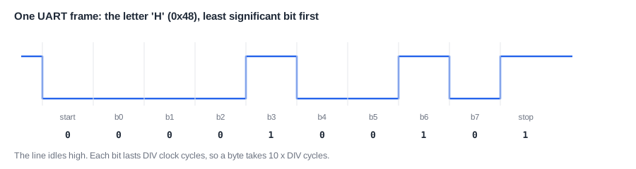
The line idles high. A start bit of 0 tells the receiver that a byte is coming, and it then samples each of the 8 data bits, least significant first, near the middle of each bit time. A stop bit of 1 returns the line to idle. That is 10 bits per byte, the common "8N1" format: 8 data bits, no parity, 1 stop bit. An optional parity bit can detect single-bit errors.
The bit time comes from the SoC clock, through a divider: each bit lasts DIV clock cycles. At 100 MHz and a DIV of 868, the baud rate is about 115,200, a common value. A receiver usually samples several times per bit, and takes the majority value, so that noise has less effect. Its sampling is resynchronized at each start bit, which is why small clock mismatches between the two ends are tolerated.
The FIFO
A byte takes 10 bit times, which at any useful baud rate is hundreds or thousands of processor cycles. If the UART could hold only one byte, the processor would wait for each one. So UARTs have a FIFO, a first-in, first-out buffer, of a few to dozens of bytes. Software can write several bytes quickly and do something else while they go out.
A FIFO doesn't remove the wait, it only postpones it. In one small SoC with an 8-byte FIFO, a test program sending a long message by polling read the status register about 13 times per byte, because once the FIFO was full, each new byte had to wait for one to leave. That was a burst of 256 bytes, much longer than the FIFO. Polling, Interrupts and DMA shows how interrupts or DMA let the processor do other work instead.
Registers
A minimal UART needs just a few registers:
| Register | Access | Purpose |
|---|---|---|
| TXDATA | write only | writing a byte adds it to the transmit FIFO |
| RXDATA | read only | reading takes a byte from the receive FIFO |
| STATUS | read only | FIFO full, FIFO empty, busy, error flags |
| DIV | read and write | clock cycles per bit |
| CTRL / IRQ | read and write | enable, interrupt enables and status |
The exact meaning of each status bit matters. A "busy" bit that is clear while bytes are still waiting in the FIFO caused a real bug in one small SoC: a program that waited for "not busy" before shutting down lost its last characters. The System Architecture Spec tells the story.
Quick Check
Q: A UART runs at 100 MHz with a DIV of 16. How long does one byte take, and how many bytes per second can it send?
Show Answer
One byte is 10 bits x 16 cycles = 160 cycles, or 1.6 µs at 100 MHz. That gives 625,000 bytes per second.
The Timer
A timer counts clock cycles, and it can raise an interrupt when the count reaches a chosen value. Operating systems use it to switch between tasks many times per second, firmware uses it to wait for exact delays, and every protocol with a time-out depends on one.
The simplest design has two registers. A counter increases by one on every tick, and a compare register holds the deadline. The timer raises its interrupt while the counter is greater than or equal to the compare value. Software sets the next deadline by writing the compare register, which also clears the interrupt. RISC-V defines exactly this arrangement, with the registers mtime and mtimecmp, so that operating systems can rely on it.
Two design choices matter. The first is width. At 100 MHz a 32-bit counter wraps around after about 43 seconds, which software must then handle, and bugs at the wrap are common. A 64-bit counter takes thousands of years to wrap, which is why RISC-V uses 64 bits. On a 32-bit processor, reading 64 bits takes two loads, and the low half may wrap between them, so software reads high, low, then high again, and retries if the high half changed. The second is the reset value of the compare register. If it resets to 0, the interrupt condition is true from the first cycle. Setting it to the maximum value means no interrupt fires until software sets a deadline. Clocks and Resets in a System uses this example.
Timers come in other forms too: down-counters that reload automatically, for a periodic tick; capture timers that record the time an input pin changed, for measuring pulses; and pulse-width modulation (PWM) timers that drive a pin high for a chosen part of each period, for motors and LED brightness. A watchdog is a timer that resets the chip if software stops responding, as Timers and Watchdogs explains.
GPIO
GPIO, general-purpose input and output, lets software drive or read pins directly. It is how firmware turns on an LED, reads a button, or controls a chip select. The core of a GPIO block is two registers: OUT, whose bits drive the pins, and IN, which reads the pins' current levels. Real blocks add more:
- a direction register to choose input or output per pin;
- set and clear registers, so one pin can be changed without a read-modify-write of the whole register, which avoids a race with an interrupt handler;
- interrupt on a rising or falling edge, or a level, per pin;
- pull-up or pull-down resistors, and drive strength, which are set in the pad or I/O cell.
An input from a pin is asynchronous: it can change at any moment, with no relation to the chip's clock. So each GPIO input passes through a synchronizer, two flip-flops, before the logic uses it, as Clock Architecture and Clock Domain Crossings explains. A button also bounces mechanically when it is pressed, and produces many edges, so firmware or hardware must debounce it.
On most chips, each pin is shared by several functions. A pin multiplexer, controlled by registers, decides whether a given pin is a GPIO, a UART transmit line or an SPI clock. Getting the pin mux right is a large part of bringing up a new board.
Where Is This Used?
Even the largest SoC still has UARTs, timers and GPIO: a debug console, the operating system tick, power and reset control, and LEDs on development boards. A microcontroller is mostly peripherals by count, with dozens of instances: several UARTs, SPI and I2C controllers, many timer channels, analog-to-digital converters, and a GPIO block for every port of pins. Choosing which peripherals and how many is a major part of defining a microcontroller product line.
What They Cost
Peripherals are small. In one small SoC built in a 130 nm process, the UART was about 7 percent of the area of its five-stage processor core, the timer about 9 percent, and the GPIO about 2 percent. The timer is larger than the UART, though it seems simpler. The reason is width: it holds two 64-bit registers, and a 64-bit comparator, and every bit of a register costs a flip-flop. A UART's FIFO costs far more if it grows from 8 bytes to 64.
Because they are small, chips often contain many copies, and their cost is in pins, verification and software, more than in area. Each instance needs a driver, registers in the spec, connections in the top level, and tests.
Other Common Peripherals
A quick tour of others found on most chips:
| Peripheral | What it does |
|---|---|
| SPI | fast serial bus with a clock, for flash, sensors and displays |
| I2C | two-wire bus with addresses, for many slow devices on one bus |
| ADC and DAC | convert between analog voltages and numbers |
| Real-time clock | keeps the date and time from a slow crystal, even in sleep |
| CRC and crypto blocks | compute checksums or encryption faster than software |
| USB, Ethernet, CAN | larger interfaces, usually with their own DMA |
The Bus Protocols tutorial covers several of these interfaces in detail.
Quick Check
Q: An interrupt handler and the main loop both change bits in the same GPIO OUT register using read-modify-write. What can go wrong, and how do set and clear registers help?
Show Answer
If the interrupt arrives between the main loop's read and write, the main loop writes back the old value and undoes the handler's change. Set and clear registers change only the chosen bits in one write, so there is nothing to interrupt.
Testing a Peripheral
Peripherals are tested at two levels. Alone, a test environment drives the bus and watches the pins: it checks each register's reset value and access type, sends bytes and checks the frames on the wire with a model of the device at the other end, and covers corners such as a full FIFO, a framing error or a timer wrapping around. In the SoC, real firmware on the processor drives the peripheral through its driver, so that the register map, interrupt routing, clocking and pin multiplexing are all exercised together. Bugs found in the second kind of test are often integration bugs, not bugs in the peripheral.
Common Mistakes
Mistake #1: Mismatched baud rates
If the divider is computed from the wrong clock frequency, the receiver samples at the wrong times and gets garbage. Check the actual peripheral clock, which may be divided from the processor clock.
Mistake #2: Reading a 64-bit timer badly on a 32-bit core
Reading the low half and then the high half can mix two different moments if the low half wraps in between. Read high, low, high, and retry if the two high values differ.
Mistake #3: Forgetting synchronizers on inputs
A GPIO or UART receive pin connected straight to logic can go metastable, and cause rare failures. Every asynchronous input needs a synchronizer.
Practice Exercise
Challenge: Set Up a UART
A UART uses 8N1 framing, and its clock is 50 MHz. These numbers are assumptions for this exercise. (a) What DIV value gives the closest rate to 115,200 baud? (b) What is the error of that rate, in percent? (c) How long does a 64-byte message take to send? (d) With a 16-byte FIFO, how long can the processor go away after filling it before the line falls idle?
Hint
DIV = clock / baud. A byte takes 10 bits.
Solution
(a) 50,000,000 / 115,200 = 434.03, so DIV = 434. (b) 50,000,000 / 434 = 115,207 baud, an error of about 0.006 percent, far inside the roughly 2 to 3 percent that a UART tolerates. (c) 64 x 10 = 640 bits, at 115,207 per second, about 5.6 ms. (d) 16 bytes x 10 bits = 160 bits, about 1.39 ms, plenty of time for other work.
Summary
- A peripheral exposes a few registers on a slow bus and does one job at the pins.
- A UART sends 10-bit frames at a rate set by a clock divider, and a FIFO lets software hand over several bytes at once.
- A timer compares a counter with a deadline, and 64-bit counters avoid wrap-around bugs.
- GPIO drives and reads pins, needs synchronizers on inputs, and is shared with other functions through a pin mux.
- Peripherals are small in area, but each adds pins, drivers and verification.
