
Two numbers describe how fast data moves in a system. Latency is the time one access takes, from request to answer. Bandwidth is the amount of data moved per unit of time. They are related but not the same, and confusing them is one of the most common causes of wrong design decisions: a wider bus does nothing for a processor that waits on one value at a time, and a faster memory does nothing for a program limited by a slow device. This article defines both, shows how they connect, applies them to the memories and peripherals of a small SoC, and works out what limits real programs.
13 min read | Beginner
What You'll Learn
- Define latency and bandwidth and convert between their units
- Compute bandwidth from access size, latency and the number of accesses in flight
- Distinguish peak bandwidth from the bandwidth a program achieves
- Identify whether a program is limited by latency, by bus bandwidth or by a device
Latency: How Long One Access Takes
Latency is the time from issuing a request to receiving its answer. Inside a chip it is usually counted in clock cycles; to compare systems with different clocks, it is converted to nanoseconds by multiplying by the clock period. At 100 MHz, where a cycle is 10 ns, a 4-cycle access takes 40 ns.
Every step between the manager and the data adds latency: the logic that decides where the access goes, each handshake on the way, each register stage that holds the request for a cycle, the memory itself, and the same again on the way back. That is why latency grows with distance in the system. On a small example SoC, three paths have very different values:
| Target | Path from the core | Latency | At 100 MHz |
|---|---|---|---|
| TCM | inside the CPU subsystem, no bus | 1 cycle | 10 ns |
| system SRAM | AXI4-Lite port, interconnect, SRAM | 4 cycles | 40 ns |
| peripheral (UART, timer, GPIO) | AXI4-Lite port, interconnect, APB bridge, peripheral | 6 cycles | 60 ns |
The peripheral path costs two cycles more than the SRAM because of the bridge: APB, the simple peripheral bus, needs a setup cycle and an access cycle for every transfer, and the bridge needs time to translate between the two protocols. In large systems the numbers are much larger. A read from DRAM through a big interconnect typically takes on the order of 100 ns, which is hundreds of cycles for a processor running at several GHz.
For a processor, latency is time it may have to wait. A simple core waits for every bus access before it continues, so each one costs its full latency in run time. Buses and Transactions follows one 4-cycle SRAM write handshake by handshake.
Bandwidth: How Much Data per Second
Bandwidth, also called throughput, is how much data moves per unit of time. Inside a chip it is natural to count bytes per cycle; to compare systems it is converted to bytes per second by multiplying by the clock frequency. At 100 MHz, 1 byte per cycle is 100 million bytes per second, 100 MB/s. Large systems quote GB/s, and serial interfaces usually quote bits per second (Mbit/s, Gbit/s); a byte is 8 bits, so 1 Gbit/s is at most 125 MB/s, and less once the protocol's overhead bits are removed.
From Latency to Bandwidth
When a manager can have only one access in progress at a time, as in a simple CPU subsystem, bandwidth follows directly from latency. One 4-byte access every L cycles moves 4 / L bytes per cycle:
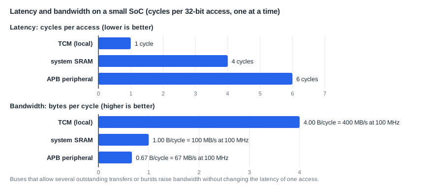
That gives 4 bytes per cycle from the TCM, 1 from the system SRAM and 0.67 from a peripheral: 400, 100 and 67 MB/s at 100 MHz. Here, a longer latency directly means a lower bandwidth.
Raising Bandwidth Without Changing Latency
The link between the two is not fixed. A manager that sends its next request before the previous answer has come back keeps several transactions outstanding at once. If N accesses are in flight and each takes L cycles, N accesses complete every L cycles:
bandwidth = accesses in flight x bytes per access / latency
A second technique is the burst: one address followed by several data transfers to consecutive locations, so that the address handshake and much of the latency are paid once for many words. Full AXI supports both outstanding transactions and bursts; AXI4-Lite supports neither, which keeps it simple. Outstanding Transactions and Bursts measures what they gain.
The formula also works the other way around: to reach a given bandwidth over a path with a given latency, a manager needs enough accesses in flight. This is why the memory interfaces of high-performance processors track dozens of outstanding misses at once.
Quick Check
Q: A memory has a latency of 20 cycles, and the bus allows 4 outstanding 4-byte reads. What bandwidth can a manager reach at best, and what would it be with only one read in flight?
Show Answer
With 4 in flight: 4 x 4 bytes / 20 cycles = 0.8 bytes per cycle. With one: 4 / 20 = 0.2 bytes per cycle. The latency is the same 20 cycles in both cases; only the overlap differs.
Peak Bandwidth and Achieved Bandwidth
The figures above are peak bandwidth: what the path delivers if the manager does nothing but access it back to back. Real programs also compute between accesses, so the bandwidth they achieve is lower. Take a test program that copies a 4 KB buffer from the TCM into the system SRAM and then reads the copy back to compute a checksum. Over the whole run it moved about 0.24 bytes per cycle to and from the SRAM, against a peak of 1 byte per cycle.
The program reaches about a quarter of the peak. Between its SRAM accesses the core reads the source buffer from the TCM, increments pointers, tests the loop condition and updates the checksum. The SRAM path sits idle most of the time, waiting for the next request.
This gap is normal, and it has a consequence for design: buses and memories are sized from the bandwidth that real use cases demand, plus a safety margin, not from what a single benchmark could use at peak. A system with every path sized for peak bandwidth is large and power-hungry.
Quick Check
Q: Would doubling the system SRAM's peak bandwidth, for example with a 64-bit wide path, make copy_sram twice as fast?
Show Answer
No. The program uses only a quarter of the present peak and moves one 32-bit word per access, so a wider path would sit idle too. What it waits for is the 4-cycle latency of each access; lowering that, or keeping the buffer in the TCM, would help.
When a Device Sets the Pace
Sometimes neither the bus nor the memory is the limit, but the device at the end. A UART sends one bit at a time on a single wire. A typical UART sends each byte as a 10-bit frame (a start bit, 8 data bits and a stop bit), and in this example each bit lasts 16 clock cycles. So one byte takes 10 x 16 = 160 cycles, a device bandwidth of 1 / 160 of a byte per cycle, 0.625 MB/s at 100 MHz. That is about 100 times slower than the bus path to a peripheral, which delivers 0.67 bytes per cycle.
A small test program, called stream here, sent 256 bytes over the UART as fast as the UART allowed, as a data logger would, at two UART speeds: DIV = 16 and DIV = 4, where the divider setting DIV is the number of clock cycles per bit.
In both cases the run time was within about 3 percent of the UART's minimum. Making the UART four times faster made the program 3.9 times faster. The bus latency hardly matters; the device's bandwidth sets the pace. The status reads show where the waiting went: at the slower speed, the core read the UART's status register about 13 times per byte while it waited for room to send.
Where Does This Matter?
A display controller must fetch every pixel of every frame in time, so it needs a guaranteed bandwidth, while a CPU waiting for one value cares about latency. SoC architects budget both: the DRAM bandwidth of a phone chip is shared out among cameras, display, GPU and CPUs for each use case, such as recording 4K video, and latency-sensitive managers get priority in the interconnect.
A Bandwidth Budget
In a real SoC, architects add up the bandwidth that every manager needs in a use case and compare it with what the memory system can deliver. The arithmetic is simple. A display showing 1920 x 1080 pixels at 4 bytes per pixel and 60 frames per second must read:
1920 x 1080 pixels x 4 bytes x 60 frames/s = 497,664,000 bytes/s, about 498 MB/s
That traffic never stops: if the display controller does not get its pixels in time, the screen shows a glitch. A camera writing frames of the same size at the same rate needs another 498 MB/s, a video encoder reads those frames and writes compressed video, and the CPUs and GPU use DRAM too. A DRAM interface with a 32-bit data bus running at 4,266 million transfers per second delivers at most 4,266,000,000 x 4 bytes = 17 GB/s at its peak, and in practice noticeably less, because DRAM also spends time switching rows, refreshing and turning the bus around between reads and writes.
The budget tells the architect whether a use case fits, how much margin is left, and which managers need priority in the interconnect so that the display, with its hard deadline, is always served even when the CPUs are busy. Budgets like this are written into the system spec for every important use case.
Hiding Latency
Latency that cannot be removed can often be hidden. A cache keeps copies of recently used data in a small, fast memory next to the processor, so most accesses never pay the full latency of the memory behind it. Prefetching fetches data before the program asks for it, for example the next lines of an array that is being read in order. And a processor or DMA engine with many outstanding transactions keeps working while earlier requests are still on their way. All three turn a latency problem into a bandwidth or area cost, which is often the cheaper one.
Which One Limits the Program?
Before choosing a fix, find out which limit a program actually meets:
- Latency-bound: the manager waits for each access before issuing the next, and the path is mostly idle.
copy_sramis an example. Fixes: lower latency (closer memory, caches) or more accesses in flight. - Bandwidth-bound: the path is busy nearly all the time, back to back. Fixes: a wider or faster path, bursts, or less data moved.
- Device-bound: the device at the end is slower than everything in front of it, as in
stream. Fixes: a faster device, or letting the processor do other work while it waits, through interrupts or DMA.
Common Mistakes
Mistake #1: Using bandwidth to answer a latency question
A processor that waits for one value at a time is limited by latency, however wide the bus. Check which one the use case is sensitive to before choosing a fix.
Mistake #2: Designing for peak bandwidth only
Peak numbers assume back-to-back transfers that real traffic rarely produces. Measure the bandwidth the use cases actually need and the latency they tolerate.
Mistake #3: Mixing bits and bytes
Interfaces quote bits per second, memories bytes per second. A 1 Gbit/s link moves at most 125 MB/s, and less after protocol overhead: the UART here spends 10 bits on every 8-bit byte.
Practice Exercise
Challenge: TCM or SRAM, and How Fast Can It Log?
(a) Program copy_tcm does the same work as the program above, here called copy_sram, but keeps the destination buffer in the TCM. Assume it takes 27,670 cycles. Using the latencies above, predict the run time of copy_sram from its 2,048 SRAM accesses. (b) A data logger must send 1,000 bytes per second over this UART at DIV = 16, with a 100 MHz clock. What fraction of the UART's bandwidth does it use? (c) At what DIV would the UART be the bottleneck for a logger that must send 1 MB per second?
Hint
An SRAM access costs 3 cycles more than a TCM access. A UART byte takes 10 x DIV cycles.
Solution
(a) 2,048 x 3 = 6,144 extra cycles, so 27,670 + 6,144 = 33,814 cycles. A real run matched this: latency explains the whole slowdown. (b) At DIV = 16 the UART sends 100,000,000 / 160 = 625,000 bytes per second, so 1,000 bytes per second uses 0.16 percent of it. (c) 1 MB per second needs at most 100 cycles per byte, so 10 x DIV must be at most 100: DIV = 10 or less. At DIV = 16 (625,000 bytes per second) the UART cannot keep up.
Summary
- Latency is the time for one access; bandwidth is data per unit of time; cycles and bytes per cycle convert to ns and MB/s with the clock.
- With one access in flight, bandwidth = bytes / latency: 4, 1 and 0.67 bytes per cycle for TCM, SRAM and peripherals in the small example.
- Outstanding transactions and bursts raise bandwidth without changing latency.
copy_sramachieved 0.24 bytes per cycle of a 1 byte per cycle peak: it is latency-bound.streamran within about 320 cycles of the UART's minimum time at both speeds: it is device-bound.
