
An interrupt controller gathers the interrupt signals from every device on an SoC, decides which ones are enabled and which is most urgent, and delivers them to the right processor. A processor core has only a few interrupt inputs, while a chip may have hundreds of sources, so this block is what makes interrupts usable at scale. This article explains what an interrupt controller does step by step, how priority, thresholds and claiming work, how RISC-V and other architectures organize it, and how interrupts are routed in a multicore chip.
11 min read | Intermediate
What You'll Learn
- Explain why an SoC needs an interrupt controller
- Describe how gateways, priorities, enables and thresholds pick an interrupt
- Walk through the claim and complete sequence in a handler
- Describe how interrupts are routed to cores and how message-signaled interrupts work
Why a Controller Is Needed
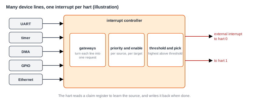
Polling, Interrupts and DMA explained what an interrupt is, and Interrupts and Interrupt Latency described how a core takes one. A RISC-V core has three machine-level interrupt inputs: external, timer and software. An SoC might have a UART, several timers, DMA channels, GPIO ports, USB, Ethernet and dozens more, each with its own interrupt line. Somebody must combine them, decide which goes first, and tell the processor which device it was. That is the job of the interrupt controller.
How It Picks an Interrupt
A typical controller, such as the RISC-V PLIC (platform-level interrupt controller), works in stages.
Gateways
Each source first passes a gateway, which turns its signal into a single pending request. Devices signal in different ways: a level interrupt stays high until software clears the cause in the device, and an edge interrupt is a short pulse. The gateway records one pending request, and won't forward another from the same source until the first has been handled. This stops a level interrupt from being taken again and again while its handler is still running. Signals from devices on other clocks are synchronized here, too.
Priority and Enable
Each source has a priority, set by software, typically from 1 to 7 or higher. Priority 0 means "never interrupt". For each target, which is usually one privilege mode of one hart (hardware thread), each source has an enable bit. A source is considered only for the targets that enable it.
Threshold and Selection
Each target has a threshold. Only pending, enabled sources with a priority above the threshold can interrupt it. Among those, the controller picks the highest priority, using the lowest source number to break ties, and raises the target's external interrupt line. Raising the threshold is how software masks all but the most urgent interrupts for a while, without touching each source's enable bit.
Claim and Complete
When the hart takes its external interrupt, the handler doesn't yet know which device caused it. It reads a claim register in the controller. The read returns the ID of the highest-priority pending source, and clears that source's pending bit, so that no other hart claims the same interrupt. The handler then services the device, and finally writes the same ID to the complete register, telling the gateway that it may accept a new request from that source:
external interrupt handler:
    id = read(CLAIM)              # which source, and mark it as being handled
    if id == 0: return            # another hart already claimed it
    handle_device(id)             # read the device, clear its interrupt cause
    write(COMPLETE, id)           # allow the next request from this source
    return with mret
The handler can loop, claiming again before it returns, to serve several pending interrupts in one entry, which saves the cost of returning and re-entering. Order matters in the device step: the cause must be cleared in the device before completing, otherwise a level interrupt fires again at once.
Quick Check
Q: Sources 3, 7 and 9 are pending, with priorities 2, 5 and 5. The target's threshold is 2. Which does the claim return, and which can't interrupt at all?
Show Answer
Source 3 has priority 2, which is not above the threshold, so it can't interrupt. Sources 7 and 9 tie at priority 5, and the lower ID wins, so the claim returns 7. Source 9 is served on the next claim.
Timers and Software Interrupts
Timer and software interrupts usually come from a separate, simpler block, because every hart needs its own. In RISC-V systems, a block often called CLINT (core-local interruptor) holds the shared time counter and one timer compare register per hart, which drive each hart's timer interrupt, plus one software-interrupt bit per hart. A software interrupt is how one hart interrupts another: writing the other hart's bit raises its interrupt. Operating systems use this to ask another core to reschedule, or to flush its TLB, as TLBs and Page Table Walks describes. Timers and Watchdogs covers timers in more detail.
Routing in a Multicore Chip
With several cores, each interrupt must go to the right place. The enables per target let software steer each source to one or more harts. Common strategies are:
- Send each device's interrupt to one core, chosen by the operating system to balance the load, or to keep a device's handling on the core that uses its data.
- Send an interrupt to several cores, and let the first to claim it handle it. The claim register makes sure only one does.
- Keep real-time interrupts on a core that runs nothing else, so their latency is short and predictable.
Linux on a multicore system lets an administrator set this per interrupt, which is called interrupt affinity.
Message-Signaled Interrupts
Wires don't scale well. A chip with hundreds of sources and many cores would need a huge number of them, and devices such as PCIe cards can't have dedicated wires at all. Message-signaled interrupts (MSIs) replace the wire with a write: the device writes a specific value to a specific address, and that write is the interrupt. An interrupt controller receives these writes and turns them into pending interrupts for the right hart.
MSIs travel through the normal interconnect, so they scale with it, and they arrive in order with the device's data writes, which removes a subtle race: with a separate wire, an interrupt could arrive before the data it announces is in memory. PCIe relies on MSIs, and RISC-V's Advanced Interrupt Architecture defines a controller for them, the IMSIC, alongside a newer wired controller, the APLIC. Arm's GIC family does the same for Arm systems.
Where Is This Used?
Every SoC with more than a handful of interrupt sources has an interrupt controller, and choosing and configuring it is part of the CPU subsystem integration. A microcontroller's controller is often built into the core, such as Arm's NVIC, with dozens of sources and very low latency. Application processors use a separate controller shared by a cluster. Virtualization adds another layer: a hypervisor must be able to deliver interrupts to guest operating systems, which modern controllers support in hardware.
Latency and Priority Design
The controller adds a little latency, typically a few cycles to synchronize and select, plus the cycles to read the claim register over the bus. That is small next to the rest of the cost in Interrupts and Interrupt Latency, but it matters for very fast interrupts. Some designs give the most urgent sources a separate, faster path, such as a dedicated non-maskable interrupt line that software cannot disable.
Priorities are assigned by the system's real-time needs. A safety shutdown signal or an audio buffer about to underrun gets the highest priority, ordinary devices are in the middle, and background tasks such as statistics counters are at the bottom. Two interrupts that can't wait for each other need different priorities, and the handler of the lower one must be short, or allow nesting, so that it doesn't delay the higher one.
Interrupt Storms
A device that interrupts far too often, through a bug or under heavy load, can keep the processor busy handling it and starve everything else. This is called an interrupt storm. Devices guard against it with interrupt coalescing: they wait until several events have happened, or a short time has passed, and raise one interrupt for all of them. Network controllers do this routinely. The operating system can also disable a misbehaving source.
Quick Check
Q: Why does a device driver usually clear the interrupt cause in the device before writing the complete register?
Show Answer
For a level-sensitive interrupt, the line stays active until the device's cause is cleared. If the handler completes first, the gateway sees the line still active and creates a new pending request, so the interrupt fires again immediately for an event already handled.
Interrupts and Sleep
Interrupts are also how a sleeping chip wakes up. When the processor runs wfi and its domain is powered down or its clock stopped, the interrupt controller itself may be off too. So a small piece of logic in the always-on domain watches the few sources that are allowed to wake the system: a button, a real-time clock alarm, a network packet, a sensor threshold. When one fires, it asks the power controller to restore power and clocks to the processor, and the interrupt is then delivered normally. Power Domains and Power Management describes that sequence. The wake-up sources are part of the system design, chosen by which events the product must respond to while asleep, and each extra source costs a little standby power. The time from a wake-up event to the first instruction of the handler can be milliseconds, far longer than a normal interrupt, which matters for products that must react quickly even from deep sleep.
Verifying Interrupts
Interrupt routing is checked at several levels. Connectivity checks confirm that each device's line reaches the right controller input, as Top-Level Integration and Connectivity Checks describes. Tests on the processor trigger each source in turn and check that the right handler runs, with the right ID. And stress tests raise many interrupts at random times, while software nests and masks them, to find race conditions in the claim and complete logic and in the drivers. Swapped interrupt lines are one of the most common integration bugs, so these tests are generated from the same source as the top level.
Common Mistakes
Mistake #1: Completing before clearing the device
A level interrupt fires again at once if the device's cause is still set. Clear the cause first, then complete.
Mistake #2: Leaving priority at 0
A source with priority 0 never interrupts, even if enabled. A new driver that forgets to set it waits forever.
Mistake #3: Mixing up edge and level sources
Configuring a level source as edge can lose events, and an edge source as level can cause repeated interrupts. The configuration must match the device.
Practice Exercise
Challenge: Set Up the Priorities
A system has four interrupt sources on one hart: an audio DMA that must be served within 20 µs, a UART that can wait 1 ms, a network controller that coalesces packets and can wait 200 µs, and a temperature alarm that must shut things down quickly. Priorities run from 1 to 7. (a) Assign priorities. (b) The audio handler takes 5 µs and the network handler 50 µs. If interrupts are not nested, can the audio deadline be missed? (c) What would you change?
Hint
Without nesting, a high-priority interrupt that arrives while a long handler runs must wait for it to finish.
Solution
(a) For example: temperature alarm 7, audio 6, network 3, UART 2. (b) Yes. If the audio interrupt arrives just after the network handler starts, it waits up to 50 µs, more than its 20 µs deadline. (c) Allow nesting, so the network handler re-enables interrupts above its own priority early on. Or shorten the network handler by moving most of its work to a lower-priority task. Or route audio to a different core.
Summary
- An interrupt controller combines many device lines into a few interrupts per hart.
- Gateways turn signals into requests; priority, enables and a threshold per target choose which one interrupts.
- Handlers claim the source ID, service the device, clear its cause, then complete.
- A separate block provides each hart's timer and software interrupts.
- Message-signaled interrupts replace wires with writes, scaling to many sources and cores.
