
Power management is how an SoC spends as little energy as possible while still doing its job: switching off the parts that aren't needed, slowing down the parts that don't need full speed, and waking quickly when work arrives. Battery life, heat, and the cost of a power supply all depend on it. This article explains where power goes, how clock gating and power gating work, what isolation and retention cells do, how a power controller sequences domains, how the power intent is described, and how sleep states are organized.
12 min read | Intermediate
What You'll Learn
- Distinguish dynamic and leakage power and what reduces each
- Explain clock gating and power gating, and when to use each
- Describe isolation cells, retention flip-flops and level shifters
- Describe how a power controller sequences domains and sleep states
Where the Power Goes
PPA Trade-offs and Amdahl's Law introduced the two kinds of power. Dynamic power is spent when signals switch, and follows activity x capacitance x voltage squared x frequency. Leakage power flows through transistors even when nothing switches, as long as they are powered. In older processes, dynamic power dominated. In modern ones, leakage can be a large share, especially in big memories and at high temperature.
The two need different cures. Dynamic power falls when signals stop switching, or when voltage and frequency drop. Leakage only falls when the voltage drops, or the power is removed entirely. An SoC uses all of these, at different scales.
Clock Gating
The cheapest saving is to stop the clock to logic that has nothing to do. With no clock edges, flip-flops don't switch, and neither does the logic they feed, so dynamic power in that logic drops to nearly zero. State is kept, and restarting takes a cycle. Clock Architecture and Clock Domain Crossings explains how gating cells work. Synthesis inserts fine-grained gating automatically on registers that hold their value, and coarse gating turns off whole blocks under software or hardware control. Clock gating does nothing for leakage, though: the logic is still powered.
Power Gating
To stop leakage, the power itself must be removed. Power gating puts a block in a power domain of its own, with large power switch transistors between it and the supply. Turning the switches off cuts both dynamic and leakage power in that domain to nearly zero. The price is that the domain loses its state, and turning it back on takes time: microseconds to milliseconds, depending on its size, because the switches must be turned on gradually to avoid a surge of current that would disturb the rest of the chip.
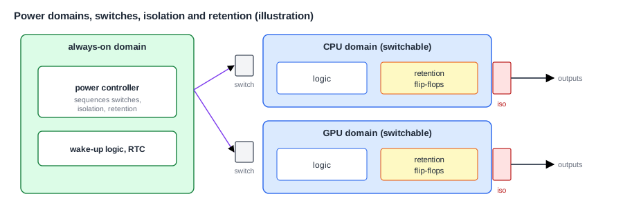
A typical SoC has several power domains: an always-on domain with the power controller, the real-time clock and the wake-up logic; a domain per CPU cluster, or per core; domains for the GPU, the video blocks, the modem, and so on. Each switchable domain can be turned off when its block is idle.
Isolation
When a domain is off, its outputs float at undefined voltages. Blocks that are still on, and read those signals, could see random values, or draw large currents through their input transistors. So every output that leaves a switchable domain passes through an isolation cell, which clamps it to a safe value, 0 or 1, while the domain is off. The safe value is chosen by meaning: a "request valid" signal must clamp to 0, so that no false request appears, and an active-low reset must clamp to its inactive level.
Retention
Losing all state means that a block must be fully re-initialized after it powers back on, which takes time and energy. Retention flip-flops keep a copy of their value in a small, separately powered latch. Before power-down, a save signal copies the state into the latches. After power-up, a restore signal copies it back. Only the important state is retained, such as configuration and a processor's architectural registers, because retention cells are larger and leak a little. Memories can also be kept in a low-voltage retention mode, in which they hold data but can't be read.
Level Shifters
Different domains may run at different voltages, for example a CPU domain lowered for power saving. A signal passing from a low-voltage domain to a higher one may not be high enough to be read as a 1. Level shifters translate signals between voltage domains. They are inserted wherever such crossings occur.
Quick Check
Q: A GPU domain is powered off. Its "interrupt request" output goes to the always-on interrupt controller. What value should its isolation cell clamp to, and why?
Show Answer
To 0, the inactive level. Otherwise the floating output could appear as a request, and the interrupt controller would wake the system for an interrupt from a block that is switched off.
The Power-Down and Power-Up Sequence
Switching a domain off and on safely needs a strict order, run by a power controller in the always-on domain:
power down:                          power up:
 1. stop new work, drain traffic      1. turn on switches gradually
 2. save state to retention cells     2. wait for the supply to settle
 3. enable isolation on outputs       3. reset the domain
 4. stop the clock                    4. start the clock
 5. turn off the power switches       5. restore state from retention
                                      6. release isolation
Each step depends on the one before it, and doing them out of order causes real failures: releasing isolation before the domain is reset passes garbage to its neighbors, and cutting power before traffic drains leaves other blocks waiting forever. A processor cluster adds its own steps, cleaning its caches and leaving the coherence protocol, as Multicore Integration and Coherent Interconnects explains. Many controllers are built as small sequencers, or even small processors running firmware, so that the sequence can be fixed after silicon.
Describing Power Intent
RTL describes logic, not power: it doesn't say which domain each block is in, where the switches go, or which outputs need isolation. That information, the power intent, is written separately in a standard format, the Unified Power Format (UPF, IEEE 1801). A UPF file lists the supplies, the power domains and their members, the switches, the isolation and retention strategies, and the legal power states. Synthesis and layout tools read it to insert the special cells, and simulators read it to model what happens when domains turn off. The Unified Power Format tutorial explains the language.
Sleep States
A product combines these mechanisms into a small set of system power states, from fully active to deepest sleep. A typical ladder:
| State | What is on | Wake-up time |
|---|---|---|
| Active | everything needed, with clocks gated where idle | none |
| Idle | cores clock-gated, waiting in wfi | tens of cycles |
| Core power-down | idle cores power-gated, others running | microseconds |
| Suspend | most domains off, DRAM in self-refresh, always-on domain running | milliseconds |
| Deep sleep | only the always-on domain, perhaps only the real-time clock | tens of milliseconds or more |
Deeper states save more power, but take longer to enter and leave, and cost energy to do so. A state is only worth entering if the time spent in it is long enough to pay back that cost, which is called the break-even time. The operating system, with the power controller, chooses a state from the expected idle time. Wake-up sources, such as a button, a timer alarm or a network packet, are handled in the always-on domain, as Interrupt Controllers describes.
Who Decides
Power decisions are split between hardware and software. Fast, local decisions are made in hardware: fine-grained clock gating every cycle, or a core gating its own clock while it waits in wfi. Slower, system-wide decisions are made by software, usually the operating system's power management code, which knows what the user is doing and what work is coming. It asks for a power state through an interface to firmware running on the power management processor, which carries out the sequence. Splitting it this way keeps the policy flexible, since it can be updated with software, while the risky low-level sequences stay in carefully verified hardware and firmware.
The power supply is part of the system too. The chip's supplies usually come from a separate power management IC (PMIC) on the board, with several regulators whose voltages the SoC can set over a serial bus. Switching off a whole supply saves even the leakage of the power switches, but it takes longer to turn back on. Architects plan the chip's power domains together with the PMIC's regulators, so that each group of domains that turns off together shares a supply, and the board design and the chip design agree on every rail.
Where Is This Used?
A phone spends most of its life in suspend, with its screen off, waking every so often to check for messages, and it lasts days on a battery largely because of how little it uses in that state. A modern phone chip has dozens of power domains and a dedicated power management processor. A small sensor microcontroller does the same on a smaller scale: it sleeps at microamps for seconds at a time, wakes for a millisecond to take a reading, and goes back to sleep, as the power budget in From Use Cases to Requirements works out.
Verifying Power Management
Power management adds behavior that ordinary RTL simulation doesn't show: what happens when a domain's power is cut, or when isolation is missing. Simulators that read the UPF model these: they corrupt the state of a powered-off domain, and check that isolation holds outputs at their safe values. Static tools check that every crossing between domains has the right isolation and level shifting. Tests run the full power-down and power-up sequences of every domain, many times, while traffic continues elsewhere. Power bugs found after tape-out are among the most expensive, because a chip that can't sleep may be useless as a product.
Quick Check
Q: A block leaks 2 mW when on and idle. Powering it down and up costs 10 µJ in total. What is the shortest idle period for which switching it off saves energy?
Show Answer
The saving is 2 mW x t, and it must exceed 10 µJ: t = 10 µJ / 2 mW = 5 ms. For shorter idle periods, staying on, clock-gated, is better.
Power management also needs measurement. Many chips include on-chip power or current monitors and counters of how long each domain spent in each state, so that software can see where the energy went and tune its policy, and designers can compare the silicon against their estimates.
Common Mistakes
Mistake #1: Forgetting isolation on an output
A floating output from a powered-off domain can cause false requests or excess current in the always-on logic. Every output leaving a switchable domain needs isolation, with the right clamp value.
Mistake #2: Wrong order in the power sequence
Releasing isolation before reset, or cutting power before traffic drains, causes failures that are hard to trace. Follow a fixed, verified sequence.
Mistake #3: Entering deep sleep for short idle periods
If the idle time is below the break-even time, deep sleep costs more energy than it saves. Choose states from the expected idle time.
Practice Exercise
Challenge: Pick a Sleep State
A device is idle for 50 ms between bursts of work. These numbers are assumptions for this exercise. Idle with clocks gated uses 20 mW. Suspend uses 1 mW, and entering and leaving it costs 300 µJ and 4 ms. Deep sleep uses 0.1 mW, and costs 2 mJ and 30 ms. (a) What energy does each option use over one 50 ms idle period? (b) Which is best? (c) If the idle period were 2 seconds, which would be best? (d) What else limits the choice?
Hint
Energy = power x time in the state + transition energy. Ignore the power during the transition time for simplicity.
Solution
(a) Idle: 20 mW x 50 ms = 1 mJ. Suspend: 1 mW x 46 ms + 0.3 mJ = 0.346 mJ. Deep sleep: 0.1 mW x 20 ms + 2 mJ = 2.002 mJ. (b) Suspend. (c) Idle: 40 mJ. Suspend: about 2 + 0.3 = 2.3 mJ. Deep sleep: about 0.2 + 2 = 2.2 mJ, slightly better. (d) Wake-up latency: deep sleep takes 30 ms to wake, which may be too slow if work must start quickly.
Summary
- Dynamic power falls with less switching or lower voltage and frequency; leakage only falls with lower voltage or no power.
- Clock gating stops switching and keeps state; power gating stops leakage but loses state.
- Switchable domains need isolation on their outputs, retention for important state, and level shifters between voltages.
- A power controller runs a strict sequence to switch domains off and on, and power intent is described in UPF.
- Sleep states trade power against wake-up time, and are worth entering only beyond their break-even time.
