
Reset architecture is the plan for how every part of an SoC is put into a known state: what can cause a reset, which parts each cause resets, in what order the parts are released, and how reset signals reach every flip-flop safely. Reset domain crossings are the places where a signal passes from logic that can be reset to logic that isn't being reset at the same moment, and they can corrupt state in ways that look like random hardware faults. This article explains reset sources and controllers, synchronous and asynchronous resets, reset sequencing, reset domains and how to cross them safely.
11 min read | Intermediate
What You'll Learn
- List the sources of reset in an SoC and what each one resets
- Explain asynchronous assert, synchronous release, and why it matters
- Design a reset sequence for an SoC's domains
- Explain reset domain crossings and how to make them safe
Why Reset Is Hard
Clocks and Resets in a System explained that reset puts flip-flops into known values before anything runs. In a single block, that is simple: one reset input, held for a few cycles, then released. In a whole SoC, it is not. Different parts must be reset for different reasons, at different times, and some must keep their state while others are reset. A watchdog that resets the processor must not reset the register that records why the reset happened. A peripheral reset by its driver must not leave a bus transaction half finished. And every reset must be released cleanly, on a clock edge, or flip-flops can go metastable just as they start.
Reset Sources
A typical SoC has several sources of reset, collected by a reset controller:
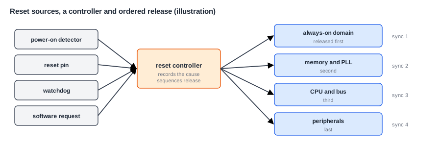
- Power-on reset (POR): a detector holds the chip in reset until the supply voltage is stable. Everything is reset.
- External reset pin: a button or a supervisor chip on the board resets the system.
- Watchdog reset: the watchdog expired, as Timers and Watchdogs describes.
- Software reset: firmware requests a reset of the whole system or of one block.
- Debug reset: a debugger resets the cores while keeping its own connection alive.
- Brown-out reset: the supply voltage dropped too low to operate safely.
Each source resets a defined set of domains. A watchdog reset might reset the cores and buses but keep the always-on domain and its registers. A debug reset resets the cores but not the debug logic, or the debugger would disconnect. The reset controller records which source caused the last reset, in a register that survives it, so that boot code can tell a cold start from a recovery.
Asynchronous Assert, Synchronous Release
A reset can act on a flip-flop in two ways. A synchronous reset is part of the logic in front of the flip-flop: it takes effect at the next clock edge. It needs a running clock, which may not exist at power-up. An asynchronous reset acts on the flip-flop directly, at once, with or without a clock. That is useful for asserting reset, since the chip goes into a safe state immediately, but dangerous for releasing it. If the reset is released just before a clock edge, inside the flip-flop's recovery window, the flip-flop can go metastable, and flip-flops released in the same cycle may come out of reset on different edges.
The standard solution combines the two: assert asynchronously, release synchronously. A reset synchronizer, two flip-flops in each clock domain, makes sure the release reaches the domain's flip-flops aligned to its own clock. Reset goes in at once, and comes out cleanly on a clock edge. Every clock domain needs its own reset synchronizer, because its release must line up with its own clock.
Quick Check
Q: Why can't one reset synchronizer serve two clock domains?
Show Answer
A synchronizer aligns the release to one clock. In a second domain with an unrelated clock, that release arrives at an arbitrary moment, with the same risk of metastability as an unsynchronized release. Each domain needs a synchronizer on its own clock.
Reset Sequencing
Blocks depend on each other, so they must come out of reset in the right order. A typical sequence:
- The always-on domain comes out first, with the power management and the reset controller itself.
- The PLLs are started, and the controller waits for them to lock.
- Memories, the interconnect and the clocks to the rest of the chip are released.
- The boot core is released, and starts at its reset vector, as Boot ROM and the Boot Flow describes.
- Peripherals and other cores are released by software, as they are needed.
The reason is simple: a core released before the memory it fetches from is ready would fetch garbage, and a bus manager released before the interconnect would send transactions nobody can answer. Many controllers also hold reset for a set number of cycles after each step, and check that clocks are running before releasing the blocks that use them.
Reset Values
Not every flip-flop needs a reset. Control state does: state machines, valid bits, enables and counters must start in known values. Data registers in a pipeline, or the contents of a FIFO, often don't, because the logic ignores them until a valid bit says otherwise. Leaving out reset where it isn't needed saves area and routing, and makes timing easier. The choice must be made carefully, though: a flip-flop without reset starts with a random value, and simulation often hides that, because many simulators start every register at a known value. Clocks and Resets in a System gives an example of a reset value chosen deliberately.
Reset Domains
A reset domain is the set of flip-flops that are reset together, by the same reset signal. An SoC has many: one per block that can be reset alone, plus the always-on domain, the debug domain, and so on. Being able to reset one block alone is useful: a driver can recover a hung peripheral without rebooting the system, and a crashed accelerator can be restarted.
Reset Domain Crossings
When a signal goes from one reset domain to another, a reset domain crossing (RDC) problem can occur, even if both are on the same clock. Suppose block A is reset while block B is not. At the moment A's reset is asserted, its flip-flops change asynchronously, at any time within B's clock cycle. If one of A's outputs feeds a flip-flop in B, that flip-flop can see its input change at a bad moment, and go metastable or capture a wrong value, exactly as in a clock domain crossing.
There is also a functional problem. If A is reset in the middle of a bus transaction with B, B may wait forever for a response that will never come, or receive a response to a request that A has forgotten. So a block being reset alone must first be brought to a safe state:
- Stop new transactions, and wait for those in flight to finish. This is called draining or quiescing.
- Isolate the block's outputs, holding them at safe values while it is in reset.
- Then assert reset, wait, release it synchronously, and remove the isolation.
Interconnects support this with a bus fence or quiesce handshake: the block signals that it wants to stop, the interconnect stops sending it new requests and reports when all outstanding ones are done.
Where Does This Matter?
Reset bugs are notoriously hard to find once the chip is built. A chip may work perfectly after power-on, then fail once in a hundred watchdog resets, because some block's state was not reset by that source, or a crossing captured a glitch. Verification teams therefore run dedicated reset tests: resets of each kind, at random moments, in the middle of traffic, followed by checks that the system recovers correctly. Structural RDC tools, like CDC tools, find every crossing between reset domains and check that each is protected.
Glitches on Reset
An asynchronous reset input is sensitive to glitches: a short pulse caused by noise, or by combinational logic, can reset flip-flops when nobody intended it. So reset signals are generated by flip-flops, never directly by logic, and the reset pin passes through filtering and a synchronizer. Reset trees are also built carefully in physical design, like clock trees, so that a reset reaches every flip-flop in its domain within the required time.
Documenting the Reset Architecture
The spec contains a reset section: every source, which domains each one resets, the release sequence and its timing, which registers survive which resets, and every reset domain crossing with its protection. Software needs this as much as hardware: a driver must know whether resetting its block clears its configuration, and boot code must know which registers it can trust after a watchdog reset.
Quick Check
Q: A DMA engine is reset alone while it has three writes outstanding to the memory controller. What can go wrong, and what should happen first?
Show Answer
The memory controller still holds the three writes and will return responses to a DMA engine that has forgotten them, which may confuse its new state, or the reset may cut a transaction in half on the bus. The engine should first stop issuing, wait for the outstanding responses, and isolate its outputs, then be reset.
Reset and Power Domains Together
Reset domains and power domains are related but not the same. When a power domain is switched off and back on, its flip-flops lose their state, so it must come out of power-up with a reset, in the same careful order as at chip power-on. If the domain has retention flip-flops, which keep some state while the power is off, those must not be reset on the way back up, or the saved state is lost. The power controller and the reset controller therefore work as a pair, and the sequence for each domain, isolate, save, power down, power up, reset, restore, release isolation, is designed and verified as one, as Power Domains and Power Management explains.
Common Mistakes
Mistake #1: Releasing an asynchronous reset without a synchronizer
Flip-flops released near a clock edge can go metastable or start on different cycles. Release every domain's reset through a synchronizer on its own clock.
Mistake #2: Resetting a block in the middle of a transaction
Its partners may hang or receive orphaned responses. Quiesce the block, isolate its outputs, then reset it.
Mistake #3: Trusting simulation's initial values
A simulator that starts registers at zero hides missing resets. Run tests with random initial values on all registers without reset.
Practice Exercise
Challenge: Design a Reset Plan
A small SoC has an always-on domain with a real-time clock and the reset controller, a PLL, a CPU with a TCM, an interconnect, a UART and a DMA engine. (a) Write a release sequence after power-on. (b) A watchdog fires. Which domains should it reset, and which should keep their state? (c) The UART driver wants to reset only the UART after an error. What must happen before and after? (d) Which register must survive every reset except power-on?
Hint
Release what others depend on first. The always-on domain keeps time and records causes.
Solution
(a) Always-on domain, then start the PLL and wait for lock, then the interconnect and TCM, then the CPU, then the UART and DMA as software enables them. (b) Reset the CPU, interconnect, UART and DMA; keep the always-on domain, so the time and the reset cause survive. (c) Before: stop new UART accesses, let any pending bus transaction finish, and mask its interrupt. Assert and release its reset through its synchronizer, then reconfigure it and unmask the interrupt. (d) The reset cause register, so boot code knows what happened.
Summary
- Resets come from power-on, the pin, the watchdog, software, debug and brown-out, and each resets a defined set of domains.
- Assert reset asynchronously and release it synchronously, with a synchronizer in each clock domain.
- Release domains in order: always-on, clocks, memories and interconnect, then cores and peripherals.
- Crossings between reset domains can capture glitches or leave transactions half done.
- Quiesce and isolate a block before resetting it alone, and record which registers survive which reset.
